700MM Tigercat REALISTIC RETRACT & FLAPS INSTALLED RIGID STRONG DURABLE EPO STABLE SMOOTH FLYING PERFORMANCE FMSMODEL.
WARNING: Read the ENTIRE instruction manual to become familiar with the features of the product before operating. Failure to operate the product correctly can result in damage to the product, personal property and cause serious injury. This is a sophisticated hobby product and NOT a toy. It must be operated with caution and common sense and failure to do so could result in injury or damage to the product or other property. This product is not intended for use by children without direct adult supervision.
Table of Contents Introduction ··························································································································3 Contents of Kit ························································································································4 Model Assembly ······················································································································5 ···················································································
Wingspan: 1700mm (66.9in) Overall Length: 1484mm (58.4in) Flying Weight: Around 5450g (192.2oz) Motor Size: Brushless 4250-KV440*2 Wing Load: 110g/dm² ( 0.25oz/in²) Wing Area: 49.5dm² ( 767.3sq.in) ESC: 60A x 2 with 10A UBEC Servo: 13g metal analog x 7, 17g metal digital x 5 Contents of Kit Before assembly, please inspect the contents of the kit. The photo below details the contents of the kit and labels.
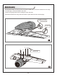
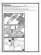
Model Assembly 1.Unpack the nacelles, connect the servo connectors CH5B, CH5C to the servo extensions in the wings as shown (fig1). Connect the ESC to the motor. Notice: Wrong plug would result in damage to motor and servo. 2.Install the nacelles to the wings and secure them in place with the screws included (fig2). CH5B and CH5C A B C fig1 HKM3.
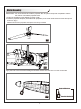
Model Assembly 1.Slide the wing tube into the fuselage. Install the left and right wing (with nacelles on) over the wing tube and into the wing slot of the fuselage (fig3). Notice: The connectors on both sides should be attached precisely and firmly. 2.Secure the left and right wings to the fuselage using the screws included (fig4). 3.
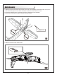
Model Assembly IMPORTANT: It is recommended to install the propeller after all system setups are completed to reduce the chance of accidental propeller strike. 1.Screw the propellers to the adapter as shown. (fig6) 2.Install the propeller adapters (assembled with propellers) to the motor shaft and then screw with spinner as shown. (fig7) NOTICE: Ensure the propeller and spinner are firmly-screwed. fig6 fig7 Apply the nose cone to the front fuselage as showed. Ensure the nose cone is on the correct side.
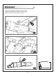
Model Assembly 1.Slide the horizontal tail tubes into the holes in the rear of the fuselage. Ensure the shorter one is put in front and the longer one in the back. Ensure the control horn faces down as shown. 2.Connect the elevator servo connectors to the servo extensions in the fuselage. 3.Secure the horizontal tail in place using the included screws. HKM3.0*16 fig9 1.Slide the oil tank into the rail as shown.
Model Assembly 1.Glue the airspeed tube in place as shown. (fig11) 2.Screw the machine guns in place as shown. (fig12) 3.Glue the antenna in place as shown.
Battery installation 1.Pull back on the release button and remove the battery hatch. 2.Apply the hook tape to the cable end of the battery(fig 14). 3.Make sure the battery is secured using the hook. Note: you may need to relocate the battery position to achieve the correct CG for your model. fig14 Connectors Diagram SERVO LANDING GEAR LED BLACK BLACK SERVO LANDING GEAR LED CAUTION:When connecting the single plug, make sure the positive and negative terminals are in the right direction.
Get your model ready to fly Important ESC and model information 1. The ESC included with the model has a safe start. If the motor battery is connected to the ESC and the throttle stick is not in the low throttle or off position, the motor will not start until the throttle stick is moved to the low throttle or off position. Once the throttle stick is moved to the low throttle or off position, the motor will emit a series of beeps.
Check the control throws The suggested control throw setting for FMS MODEL are as follows (dual rate setting): 24 26 30 20 22 26 Tips: On first flight, fly the model in low rate. The first time you use high rates, be sure to fly at low to medium speeds. High rate, as listed, is only for EXTREME maneuvering. Check the motor rotating direction The motor should rotate clockwise when viewing the plane from the rear.
Clevis Installation a. Pull the tube from the clevis to the linkage. b. Carefully spread the clevis, then insert the clevis pin into the desired hole in the control horn. c. Move the tube to hold the clevis on the control horn. a. d. b. e. c. f. Control Horn and Servo Arm Settings The table shows the factory settings for the control horns and servo arms. Fly the aircraft at the factory settings before making changes.
Check the C.G. (Center of Gravity) When balancing your model, adjust the motor battery as necessary so the model is level or slightly nose down. This is the correct balance point for your model. After the first flights, the CG position can be adjusted for your personal preference. 1. The recommended Center of Gravity (CG) location for your model is (70-80mm) from the leading edge of the main wing (as shown) with the battery pack installed. Mark the location of the CG on top of the wing. 2.
Before flying the model Find a suitable flying site Find a flying site clear of buildings, trees, power lines and other obstructions. Until you know how much area will be required and have mastered flying your plane in confined spaces, choose a site which is at least the size of two to three football fields - a flying field specifically for R/C planes is best. Never fly near people - especially children, who can wander unpredictably.
Flying your model Take off While applying power, slowly steer to keep the model straight. The model should accelerate quickly. As the model gains flight speed you will want to climb at a steady and even rate. It will climb out at a nice angle of attack (AOA). Flying Always choose a wide-open space for flying your plane. It is ideal for you to fly at a sanctioned flying field. If you are not flying at an approved site always avoid flying near houses, trees, wires and buildings.
Troubleshooting Problem Possible Cause Solution Aircraft will not respond to the throttle but responds to other controls. - ESC is not armed. - Throttle channel is reversed. - Lower throttle stick and throttle trim to lowest settings. - Reverse throttle channel on transmitter. Extra propeller noise or extra vibration. - Damaged spinner, propeller, motor, or motor mount. - Loose propeller and spinner parts. - Propellor installed backwards. - Replace damaged parts.
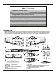
Spare parts list content FMSRB101BLU FMSRB102BLU FMSRB103BLU FMSRB104BLU FMSRB105BLU FMSRB106BLU FMSRB107BLU FMSRB108BLU FMSRB109BLU FMSRB110BLU FMSRB111BLU FMSRB112 FMSRB113 FMSRB114 FMSRB115BLU FMSRB116 FMSRB117 FMSRB118 FMSRB119 FMSRB120 FMSRB121BLU FMSRB122BLU FMSRB123-1 FMSRB123-2 FMSRB123-3 FMSRB123-4 FMSPROP049 PRKV440 PRESC007-1 PRBEC02 FMSCON005 FMSSEQ9S FMSRE034 FMSSER17MGD PR13MGAP PR13MGAR Fuselage Main wing set Horizontal stabilizer Cockpit Cowl Nacelles Oil tank Machine gun set Airspeed head
ESC instruction Wires Connection: The electronic speed controller can be connected to the motor by soldering directly, or with high quality connectors. Always use new connectors, which should be soldered carefully to the cables and insulated with heat shrink tubes. The maximum length of the battery pack wires should be within 6 inches. Solder controller to the motor wires. Solder appropriate connectors to the battery wires. Insulate all solder connectors with heat shrink tubes.
Our ESC allows you to program parameters to fit your specific needs: 1. User programmable brake setting (we recommend using brake for only folding props applications) 2. User programmable battery type (LiPo or NiCd/NiMh) 3. User programmable low voltage cutoff setting 4. User programmable factory default setting restore 5. User programmable timing settings (to enhance ESC efficiency and smoothness) 6. User programmable soft acceleration start ups (for delicate gearbox and helicopter applications) 7.
5. Timing setup: Automatic / Low / High. * Automatic – ESC automatically determines the optimum motor timing * Low (7-22 deg) – Setting for most 2 pole motors. * High (22-30 deg)-setting for motors with 6 or more poles. In most cases, automatic timing works well for all types of motors. However for high efficiency we recommend the Low timing setting for 2 pole motors (general in-runners) and high timing for 6 poles and above (general outrunners). For higher speed, High timing can be set.
Using Your New ESC Improper polarity or short circuit will damage the ESC. Therefore, it is your responsibility to double check all plugs for proper polarity and firm fit BEFORE connecting the battery pack. Alert Tones The ESC is equipped with audible alert tones to indicate abnormal conditions at power up. If the ESC can't enter into working mode after powering up, it indicates that you have not setup throttle calibration. 1.
Built-in Intelligent ESC Safety Functions 1. Over-heat protection: When the temperature of ESC exceeds 110 deg C, the ESC will reduce the output power to allow it too cool. 2. Lost Throttle signal protection: The ESC will automatically reduce output power to the motor when it detects a loss of throttle signal for 2 seconds, a subsequent loss of throttle signal beyond 2 seconds, will cause the ESC automatically to cut power to the motor.
● Never use ruptured or punctured battery cells. ● Never use battery packs that are known to overheat. ● Never short circuit battery or motor terminals. ● Always use proper insulation material for cable insulation. ● Always use proper cable connectors. ● Do not exceed the number of cells or servos specified by the ESC. Wrong battery polarity will damage the ESC and void the warranty. ● Install the ESC in a suitable location with adequate ventilation for cooling.
Motor doesn’t work after powering up the ESC. An alert tone with a single beeping tone followed by a short pause (* * * *) is emitted. The ESC is unable to detect the normal throttle signal from the receiver Check and verify that the ESC cable is connected to the Throttle channel on the receiver. Check the transmitter and receiver to verify that there is throttle signal output. (Connect a spare servo to verify throttle channel operation) Motor doesn’t work after powering up the ESC.
Decal Instruction Please choose one set of the decals according to your taste or history materials and paste it as shown. Water Decal Instructions: The above are water decals. Do not force them off from the backing paper. Please follow these directions: 1 2 3 5 6 1.Make sure your hands are dry. Cut the decal down with scissors. 2.Put the decal in water for 2 mins to bring it to full absorption. 4 3.
The bigger one is for wings. Side view Top view You need to split it after pasting.
The bigger one is for wings. Side view Top view You need to split it after pasting.
The bigger one is for wings. Side view Top view You need to split it after pasting.
The bigger one is for wings. Side view Top view You need to split it after pasting.