
User Manual

7
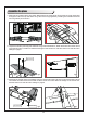
Get your model ready to fly
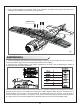
Important ESC and model information
1.
The ESC included with the model has a safe start. If the motor battery is connected to the ESC and the
throttle stick is not in the low throttle or off position, the motor will not start until the throttle stick is moved to
the low throttle or off position. Once the throttle stick is moved to the low throttle or off position, the motor will
emit a series of beeps. Several beeps with the same tune means the ESC has detected the cells of the
battery. The count of the beeps equals the cells of the battery. The motor is now armed and will start when
the throttle is moved.
2.
The motor and ESC come pre-connected and the motor rotation should be correct. If for any reason the
motor is rotating in the wrong direction, simply reverse two of the three motor wires to change the direction
of rotation.
3. The motor has an optional brake setting. The ESC comes with the brake switched off and we recommend
that the model be flown with the brake off. However, the brake could be accidentally switched on if the motor
battery is connected to the ESC while the throttle stick is set at full throttle. To switch the brake off, move the
throttle stick to full throttle and plug in the motor battery. The
motor will beep one time. Move the throttle stick to low throttle or the off position. The motor is ready to run
and the brake will be switched off.
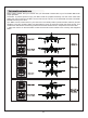
4. Battery Selection and Installation. We recommend the 14.8V 2600mAh 35C Li-Po battery. If using another
battery, the battery must be at least a 14.8V 2600mAh 35C battery. Your battery should be approximately the
same capacity, dimension and weight as the 14.8V 2600mAh 35C Li-Po battery to fit the fuselage without
changing the center of gravity significantly.
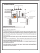
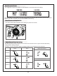
CH5B
CH5C
CH1
CH6
LE D
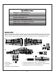
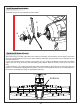
Plug for rudder servo
Plug for elevator servo
Plug for wing serial plugs
Plug for landing gear
bay doors
Plug for worm-gear
retract servo
Serial plug for the right wingSerial plug for the left wing
CH5
CH2
CH4
C H5 C
CH5 B
CH4
CH2
CH1
CH6
CH5B
CH5C
CH1
CH6
LE D
Connectors Diagram