AIRE DROP™ CEILING FAN MODEL #LP8068LAZ MODEL #LP8068LBN Español p. 20 ITEM #0921296 ITEM #0921295 ATTACH YOUR RECEIPT HERE READ AND SAVE THESE INSTRUCTIONS Serial Number Purchase Date Net Weight 17.64 lbs (8.0 kg) Questions, problems, missing parts? Before returning to your retailer, call our customer service department at 1-888-567-2055, 8 a.m.-5 p.m., EST, Monday-Friday.
Important Safety Instructions WARNING: To avoid fire, shock and serious personal injury, follow these instructions. 1. Read your owner’s manual and safety information before installing your new fan. Review the accompanying assembly diagrams. 2. Before servicing or cleaning unit, switch power off at service panel and lock service panel disconnecting means to prevent power from being switched on accidentally.
LIMITED LIFETIME WARRANTY Extends to the original purchaser of a Fanimation Fan 8. Under no circumstances may a fan be returned without prior authorization from Fanimation. The receipt of purchase must accompany authorized returns and must be sent freight prepaid to Fanimation. The fan to be returned must be properly packed to avoid damage in transit; Fanimation will not be responsible for any damage resulting from improper packaging. 9.
This manual is designed to make it as easy as possible for you to assemble, install, operate, and maintain your ceiling fan Tools Needed for Assembly blade screwdriver Materials Wiring outlet box and box connectors must be of type required by local code. The minimum wire would be a 3conductor (2-wire with ground) of the following size: Four wire connectors (supplied) Installed Wire Length Up to 50 ft. 50 - 100 ft.
Energy Efficient Use of Ceiling Fans Ceiling fan performance and energy savings rely heavily on the proper installation and use of the ceiling fan. Here are a few tips to ensure efficient product performance. Choosing the Appropriate Mounting Location Ceiling fans should be installed, or mounted, in the middle of the room and at least 7 feet from floor to the blade and 18 inches from wall to the blade. If ceiling height allows, install the fan 8 - 9 feet from floor to the blade for optimal airflow.
Electrical and Structural Requirements (Continued) Deep box with brace (Figure 3) Paired with a deep box, this hanger is meant to span between two joists and takes the place of wooden blocking. CEILING JOIST WARNING To reduce the risk of fire, electric shock, or personal injury, mount to outlet box marked acceptable for fan support of 15.9 kg (35 lbs) or less and use mounting screws provided with the outlet box.
How to Assemble Your Ceiling Fan Blades (continued) 2. Remove the two set screws and locking nuts of the downrod support from the motor assembly then retain the screws and nuts for How to Assemble Your Ceiling Fan, Step 4. (Figure 2) Downrod Support Motor Assembly Figure 2 3. Remove the six preassembled screws of the motor coupler washer from the motor assembly, then retain the screws for reinstallation in Step 7. (Figure 3) Motor Assembly Figure 3 4.
How to Assemble Your Ceiling Fan Blades (continued) 6. Re-assemble the upper housing cover and motor coupler washer as shown. (Figure 6) Motor Coupler Washer Upper Housing Cover Figure 6 7. Securely tighten the six screws that were previously removed in Step 3 on the motor assembly. (Figure 7) Motor Assembly Figure 7 How to Assemble Your Ceiling Fan 1.
How to Assemble Your Ceiling Fan (continued) 3. Route the black, white and blue wires through the downrod. (Figure 3) Black, White and Blue wires Downrod Figure 3 4. Thread downrod intothe downrod support on top of the motor. Install the clevis pin by aligning the holes in the downrod support with holes in the downrod. Secure clevis pin with hairpin clip. Tighten the two set screws with nuts in the downrod support.
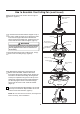
How to Hang Your Ceiling Fan WARNING To avoid possible re or shock, be sure electricity is turned off at the main fuse box before hanging. (Figure 1) MAIN FUSE BOX NOTE: If you are not sure if the outlet box is grounded, contact a licensed electrician for advice, as it must be grounded for safe operation. Figure 1 WARNING CEILING The fan must be hung with at least 7’ of clearance from oor to blades. (Figure 2) NO LESS THAN 7 FEET FLOOR Figure 2 1.
How to Wire Your Ceiling Fan NOTE: The remote unit has 32 different code combinations. To prevent possible interference from or to other remote units, simply change the combination code in the remote and receiver. Receiver Unit ON 1. To set the code on receiver unit, slide dip switches to the same positions as set on the remote. (Figure 1) 1 NOTE: Factory setting is all up. Do not use this position.
How to Wire Your Ceiling Fan (continued) 4. Once the connection has been made, slide the receiver into the hanger bracket, taking care not to pinch the wires. (Figure 5) Receiver Hanger Bracket Figure 5 Installing Your Canopy Housing NOTE: This step is applicable after the neccessary wiring is completed. 1. Remove one of the two shoulder screws in the hanger bracket. Loosen the second shoulder screw without fully removing it.
How to Assemble Your Light Kit (continued) 2. Assemble the light kit to the support bracket using the two key slots in the light kit. Replace the previously removed screw and securely tighten all three screws. (Figure 2) Light Kit Figure 2 3. Remove the three screws in the light kit and retain the screws for later. (Figure 3) Light Kit Figure 3 4. Connect the 2 single pin connectors from the LED assembly to the 2 single pin connectors from motor assembly.
How to Operate Your Remote Control 1. IMPORTANT: Using a full range dimmer switch (not included) to control fan speed will damage the fan. To reduce the risk of fire or electrical shock, do not use a full range dimmer switch to control the fan speed. (Figure 1) 2. Restore electrical power to the outlet box by turning the electricity on at the main fuse box.
How to Operate Your Remote Control (continued) 6. If airflow is desired in the opposite direction, turn the fan off and wait for the blades to stop turning. Slide the reverse switch on top of motor assembly to the opposite position and turn fan on again. (Figure 6) Reversing Switch Reverse Switch Information Season Rotation Direction Switch Position Summer Winter Counter-Clockwise Clockwise Left Right Figure 6 How to Install Your Remote Control 1.
Trouble Shooting ! WARNING For your own safety, turn off power at fuse box or circuit breaker before trouble shooting your fan. Some suggested remedies require the attention of a licensed electrician. Trouble Probable Cause 1. Fuse or circuit breaker blown. 1.FAN WILL NOT START 2. Loose power line connections to the fan, or loose switch wire connections in the switch housing. 3. Reversing switch in neutral position. 2.FAN SOUNDS NOISY Suggested Remedy 1.
Parts List Model #LP8068** Ref.
Aire Drop™ Model LP8068** Exploded-View Illustration 1 12 2 3 4 5 6 12 7 8 11 9 NOTE: The illustration shown is not to scale or its actual con guration may vary. Product/parts are subject to change without notice.
10983 Bennett Parkway Zionsville, IN 46077 Phone: 888-567-2055 Outside U.S.: 317-733-4113 FAX: 866-482-5215 www.fanimation.com 2017/11 V.
VENTILADOR DE TECHO AIRE DROP™ MODELO #LP8068LAZ MODELO #LP8068LBN ARTÍCULO #0921296 ARTÍCULO #0921295 Adjunte su recibo AQUÍ LEA Y GUARDE ESTAS INSTRUCCIONES Número de serie Fecha de compra Peso neto 8.0 kg (17.64 lbs) Preguntas, problemas, piezas faltantes? Antes de volver a la tienda, llame a nuestro Departamento de Servicio al Cliente al 1-888-567-2055, 8 a.m. - 5 pm, hora del Este, de lunes - viernes.
Instrucciones de seguridad importantes ADVERTENCIA: Siga estas instrucciones para prevenir incendios, descargas eléctricas y lesiones personales graves. 1. Lea el manual del propietario y la información de seguridad antes de instalar su nuevo ventilador. Observe los diagramas de ensamblaje adjuntos. 2. Antes de llevar a cabo el mantenimiento o la limpieza de la unidad, desconecte la electricidad en el panel de servicio y bloquee los medios de desconexión del mismo para evitar que se active accidentalmente.
GARANTÍA LIMITADA DE POR VIDA Se extiende al comprador original de un ventilador Fanimation 7. Fanimation se reserva el derecho de modificar o discontinuar un producto en cualquier momento, o sustituir cualquier pieza según lo establecido por esta garantía. 8. En ningún caso se podrá devolver un ventilador sin previa autorización por parte de Fanimation. Las devoluciones autorizadas deberán ir acompañadas del recibo de venta y deberán enviarse a Fanimation, previo pago del flete.
Este manual está diseñado para facilitar al máximo el ensamblaje, la instalación, el funcionamiento y el mantenimiento de su ventilador de techo. Herramientas necesarias para el ensamblaje Destornillador Phillips Escalera de tijera Destornillador de ¼ Pelacables Cuatro conectores de cables (incluidos) ADVERTENCIA Antes de ensamblar el ventilador de techo, consulte la sección sobre el método correcto de instalación eléctrica del ventilador (página 30).
r v El nivel de rendimiento y ahorro de energía de los ventiladores de techo dependen de su correcta instalación yuso.Acontinuaciónlepresentamosalgunassugerencias para asegurar un rendimiento eficiente del producto. r cho Uso del ventilador de techo todo el año Selección del lugar de montaje adecuado Los ventiladores de techo se deben instalar en el centro de la habitación, a 2,13 m (7 pies) de altura del piso hasta la cuchilla como mínimo y 0,5m (18 pulgadas) de las paredes hasta la cuchilla.
Requisitos eléctricos y estructurales (cont.) Uso del soporte (Figura 3) Conectado a una caja de distribución eléctrica, este colgador sirve para abarcar el espacio entre dos vigas y ocupar el lugar de bloqueo de la madera. Vigas del techo ADVERTENCIA Para reducir el riesgo de incendios, descargas eléctricas o lesiones personales, fije el ventilador a la caja de distribución eléctrica marcada como aceptable para soporte de ventilador de 15,88kg (35lb).
Cómo ensamblar las aspas del ventilador de techo (cont.) 2. Retire los dos tornillos preensamblados y las tuercas de seguridad del soporte de la varilla del ensamble del motor y guárdelos para volverlos a instalar en la Cómo ensamblar el ventilador de techo, paso 4. (Figura 2) Soporte de la varilla Motor Figura 2 3. Retire los seis tornillos preensamblados de la arandela del acoplador del motor del ensamble del motor y guárdelos para volverlos a instalar en el paso 7. (Figura 3) Motor Figura 3 4.
Cómo ensamblar las aspas del ventilador de techo (cont.) 6. Vuelva a ensamblar la cubierta de la carcasa y la arandela del acoplador del motor, como se muestra. (Figura 6) Arandela del acoplador del motor Cubierta de la carcasa superior Figura 6 7. Apriete firmemente los seis tornillos que se retiraron en el paso 3 en el ensamble del motor. (Figura 7) Motor Figura 7 Cómo ensamblar el ventilador de techo 1.
Cómo ensamblar el ventilador de techo (cont.) 3. Lntroduzca los cables de color negro, azul y blanco a través de la varilla. (Figura 3) Cables Negro, Azul y Blanco Bola para colgar Figura 3 4. Coloque el soporte de la varilla y alinee los orificios de la clavija de horquilla en ambas piezas. Instale la clavija de horquilla y asegúrela con la pinza de horquilla. Fije los dos tornillos de presión y las tuercas de seguridad en el soporte de la varilla interior.
Cómo colgar el ventilador de techo ADVERTENCIA Para evitar una posible descarga eléctrica, asegúrese de cortar la alimentación eléctrica de la caja de fusibles principal antes de colgar el ventilador. (Figura 1) PRINCIPAL CAJA DE FUSIBLES NOTA: Si no está seguro de si la caja de salida tiene conexión a tierra, pida consejo a un electricista certificado, ya que debe tener conexión a tierra para un funcionamiento seguro.
Cómo realizar la instalación eléctrica del ventilador de techo NOTA: El mando a distancia incluido en este ventilador tiene 32 combinaciones diferentes de códigos. Para evitar posibles interferencias desde o hacia otros mandos a distancia, modifique el código de combinación de su transmisor y receptor. Unidad del receptor ON 1. Para configurar el código de unidad del receptor. Deslice los interruptores de código a las mismas posiciones que en el transmisor.
Cómo realizar la instalación eléctrica del ventilador de techo (cont.) 3. Una vez realizadas las conexiones, gire los conductores hacia arriba y, con cuidado, colóquelos dentro de la caja de salida; con los conductores blancos y verdes hacia un lado y los conductores negros hacia el otro.
Cómo ensamblar su el kit de iluminación (cont.) 2. Instale la ensamble de la placa de iluminación en el soporte utilizando las dos ranuras principales de conexión. Vuelva a colocar el tercer tornillo y asegure los tres tronillos. (Figura 2) Ensamble de la placa de iluminación Figura 2 3. Extraiga uno de los tres tornillos del ensamble de la placa de iluminación y guarde los tornillos para pasos posteriores. (Figura 3) Ensamble de la placa de iluminación Figura 3 4.
Cómo utilizar su ventilador de techo 1. El uso de un regulador de la intensidad completa (no incluido) para controlar la velocidad del ventilador dañará el dispositivo. Para reducir el riesgo de incendio o descarga eléctrica, no utilice dicho regulador para controlar la velocidad del ventilador. (Figura 1) Solo para referencia visual-no ha sido diseñado para cubrir todos los tipos de controles Figura 1 2.
Cómo utilizar su ventilador de techo (cont.) 5. Funciones del control remoto: (Figura 5) Luz LED del indicador: Velocidad del ventilador Enciende el ventilador y aumenta la velocidad. Enciende el ventilador y disminuye la velocidad. Enciende el ventilador y aumenta la velocidad. Figura 5 Temporizador de apagado automático: Pulse y tanto el ventilador y la iluminación se apagarán tras 1 hora. Pulse y tanto el ventilador y la iluminación se apagarán tras 3 hora.
Mantenimiento El único mantenimiento necesario para el ventilador de techo es una limpieza periódica. Al llevar a cabo la limpieza, use sólo un cepillo suave o un paño sin pelusas, para evitar rayar el acabado. No se requieren agentes abrasivos de limpieza; los mismos deben evitarse para prevenir daños en el acabado. PRECAUCIÓN No utilice solventes para limpiar el ventilador de techo. Podrían dañar el motor o las aspas y ocasionar posibles descargas eléctricas.
Solución de problemas ʆADVERTENCIA Para su propia seguridad, desconecte la electricidad de la caja de fusibles o disyuntor antes de solucionar problemas en su ventilador. Problema 1. EL VENTILADOR NO ARRANCA Causa posible Solución sugerida 1. El fusible o el disyuntor están fundidos. 1. Controle los fusibles del circuito principal y derivado o los disyuntores. 2. Las conexiones eléctricas del ventilador o del interruptor en la caja del interruptor están flojas. 2.
Lista de piezas Model No. LP8068** N.° de Ref. Descripción 1 t Unidad del soporte de suspensión 2 Unidad del barral/de la semiesfera 3 Capuchón de techo 4 Cubierta para el tornillo del capuchón 5 Cubierta de unión del motor 6 Unidad del motor del ventilador Pieza # N.
Aire Drop™ Modelo N.
10983 Bennett Parkway Zionsville, IN 46077 Llame sin cargo al (888) 567-2055 FAX (866) 482-5215 Desde fuera de los EE.UU., llame al (317) 733-4113 Visite nuestro sitio Web en www.fanimation.com 2017/11 V.