ALL-WEATHER PYLON™ CEILING FAN MODEL #LP8177** Español p. 21 ATTACH YOUR RECEIPT HERE READ AND SAVE THESE INSTRUCTIONS Serial Number Purchase Date Net Weight 15.61 lbs (7.08 kg) Questions, problems, missing parts? Before returning to your retailer, call our customer service department at 1-888-567-2055, 8 a.m.-5 p.m., EST, Monday-Friday.
Important Safety Instructions WARNING: To avoid fire, shock and serious personal injury, follow these instructions. 1. Read your owner’s manual and safety information before installing your new fan. Review the accompanying assembly diagrams. 2. Before servicing or cleaning unit, switch power off at service panel and lock service panel disconnecting means to prevent power from being switched on accidentally.
LIMITED LIFETIME WARRANTY Extends to the original purchaser of a Fanimation Fan 8. Under no circumstances may a fan be returned without prior authorization from Fanimation. The receipt of purchase must accompany authorized returns and must be sent freight prepaid to Fanimation. The fan to be returned must be properly packed to avoid damage in transit; Fanimation will not be responsible for any damage resulting from improper packaging. 9.
This manual is designed to make it as easy as possible for you to assemble, install, operate and maintain your ceiling fan Materials Tools Needed for Assembly ne hillips head screwdriver One stepladder Four wire connectors supplied ! iring outlet o and o connectors ust e of type re uired y the local code he ini u wire would e a conductor wire with ground of the following si e: One wire stripper One lade screwdriver nstalled ire ength p to ft ft WARNING Before assembling your ceiling fan, refe
Energy Efficient Use of Ceiling Fans Ceiling fan performance and energy savings rely heavily on the proper installation and use of the ceiling fan. Here are a few tips to ensure efficient product performance. Using the Ceiling Fan Year Round Summer Season: Use the ceiling fan in the counterclockwise direction. The airflow produced by the ceiling fan creates a wind-chill effect, making you “feel” cooler.
Electrical and Structural Requirements (Continued) Brace use (Figure 3) Paired with a deep box, this hanger is meant to span between two joists and takes the place of wooden blocking. CEILING JOIST WARNING To reduce the risk of fire, electrical shock, or personal injury, mount fan to outlet box marked acceptable for fan support of 15.88 kg (35 lbs) or less. Use screws supplied with outlet box.
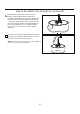
How to Assemble Your Ceiling Fan 1. Remove the hanger ball portion from the downrod/ hanger ball assembly by loosening the set screw in the hanger ball until the ball falls freely down the downrod. Remove the pin from the downrod, then remove the hanger ball. Retain the pin and hanger ball for reinstallation in Step 6. (Figure 1) Downrod Set Screw Hanger Ball Figure 1 2. Remove the hairpin clip and clevis pin from the bottom of the downrod. Retain the pin and clip for reinstallation in Step 4.
How to Assemble Your Ceiling Fan (continued) 6. Reinstall the hanger ball on the downrod as follows. Route the black, white and blue wires through the hanger ball. Position the pin through the two holes in the downrod and align the hanger ball so the pin is captured in the groove in the top of the hanger ball. Pull the hanger ball up tight against the pin. Securely tighten the set screw in the hanger ball. A loose set screw could create fan wobble. (Figure 6) Figure 6 7.
How to Hang Your Ceiling Fan WARNING To avoid possible re or shock, be sure electricity is turned off at the main fuse box before hanging. (Figure 1) Main Fuse Box NOTE: If you are not sure if the outlet box is grounded, contact a licensed electrician for advice, as it must be grounded for safe operation. Figure 1 WARNING Ceiling The fan must be hung with at least 7’ of clearance from oor to blades. (Figure 2) Floor No Less than 7 Feet Figure 2 1.
How to Wire Your Ceiling Fan NOTE: The remote unit has 32 different code combinations. To prevent possible interference from or to other remote units, simply change the combination code in the remote and receiver. 1. To set the code on receiver unit, slide dip switches to the same positions as set on the remote. If complete the receiver code setting process, put the rubber cover (included) in the receiver unit. (Figure 1) Receiver Unit ON 1 DIP 2 3 4 5 Dip Switch NOTE: Factory setting is all up.
How to Wire Your Ceiling Fan (continued) 4. Once the connection has been made, slide the receiver into the hanger bracket, taking care not to pinch the wires. (Figure 5) Receiver Hanger Bracket Figure 5 How to Install Your Canopy Housing NOTE: This step is applicable after the neccessary wiring is completed. 1. Remove one of the two shoulder screws in the hanger bracket. Loosen the second shoulder screw without fully removing it.
How to Assemble Your Light Kit Assembly or Cap 1. Remove one of the three screws in the support bracket at the bottom of the motor assembly. Retain the screw for later and slightly loosen the remaining two screws. (Figure 1) Motor Assembly Figure 1 2. Assemble the light kit to the support bracket using the two key slots in the light kit. Replace the previously removed screw and securely tighten all three screws. (Figure 2) Motor Assembly Light Kit Figure 2 3.
How to Assemble Your Light Kit Assembly or Cap (continued) 6. Assemble the LED assembly to the light kit using the two key slots. Replace the removed screw from Step 3 and secure all three screws. (Figure 6) CAUTION Light Kit The light source is designed for this specific application and can overheat if serviced by untrained personnel. If any servicing is required, the product should be returned to an authorized service facility for examination or repair. LED Assembly Figure 6 7.
How to Operate Your Ceiling Fan (continued) 3. 7R PDNH IDQ RSHUDWLRQDO LQVWDOO $ 9 EDWWHU\ LQFOXGHG LQ KDQG KHOG UHPRWH WUDQVPLWWHr ZLWK IDQ SRZHU RfI 7KHQ IROORZ WKH UHPRWH FRGH VHWWLQJ SURFHVV ,I QRW XVHG IRU ORQJ SHULRGV RI WLPH UHPRYH EDWWHU\ WRSUHYHQW GDPDJH WR WUDQVPLWWHU 6WRUH WKH UHPRWH DZD\ IURP H[FHVVLYH KHDW RU KXPLGO\ (Figure 3) 9 $ %DWWHU\ SFV Figure 3 NOTE: The remote unit has 32 different code combinations.
How to Install Your Remote Control 1. Installing Wall Holder: (Figure 1) Attach wall holder using the two provided screws. Figure 1 Maintenance 1. Periodic cleaning of your new ceiling fan is the only maintenance that is needed. When cleaning, use only a soft brush or lint free cloth to avoids cratching the finish. Abrasive cleaning agents are not required and should be avoided to prevent damage to finish. CAUTION Do not use water when cleaning your ceiling fan.
Trouble Shooting WARNING For your own safety turn off power at fuse box or circuit breaker before trouble shooting your fan. Trouble Probable Cause 1. Fuse or circuit breaker blown. 1.FAN WILL NOT START 2.FAN SOUNDS NOISY 2. Loose power line connections to the fan, or loose switch wire connections in the switch housing. 1. Check main and branch circuit fuses or circuit breakers. 2. Check line wire connections to fan and switch wire connections in the switch housings.
Parts List Model No.
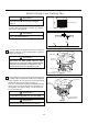
ALL-WEATHER PYLON™ Model LP8177** Exploded-View Illustration 1 14 2 3 4 5 6 7 14 8 10 9 11 Figure 1 NOTE: The illustration shown is not to scale or its actual con guration may vary. Product/parts are subject to change without notice.
10983 Bennett Parkway Zionsville, IN 46077 Phone: 888-567-2055 Outside U.S.: 317-733-4113 FAX: 866-482-5215 www.fanimation.com 2017/12 V.
™ VENTILADOR DE TECHO ALL-WEATHER PYLON MODELO #LP8177** Adjunte su recibo AQUÍ LEA Y GUARDE ESTAS INSTRUCCIONES Número de serie Fecha de compra Peso neto 7.08 kg (15.61 lbs) Preguntas, problemas, piezas faltantes? Antes de volver a la tienda, llame a nuestro Departamento de Servicio al Cliente al 1-888-567-2055, 8 a.m. - 5 pm, hora del Este, de lunes - viernes.
Instrucciones de seguridad importantes ADVERTENCIA: Siga estas instrucciones para prevenir incendios, descargas eléctricas y lesiones personales graves. 1. Lea el manual del propietario y la información de seguridad antes de instalar su nuevo ventilador. Observe los diagramas de ensamblaje adjuntos. 2. Antes de llevar a cabo el mantenimiento o la limpieza de la unidad, desconecte la electricidad en el panel de servicio y bloquee los medios de desconexión del mismo para evitar que se active accidentalmente.
GARANTÍA LIMITADA DE POR VIDA Se extiende al comprador original de un ventilador Fanimation 7. Fanimation se reserva el derecho de modificar o discontinuar un producto en cualquier momento, o sustituir cualquier pieza según lo establecido por esta garantía. 8. En ningún caso se podrá devolver un ventilador sin previa autorización por parte de Fanimation. Las devoluciones autorizadas deberán ir acompañadas del recibo de venta y deberán enviarse a Fanimation, previo pago del flete.
Este manual está diseñado para facilitar al máximo el ensamblaje, la instalación, el funcionamiento y el mantenimiento de su ventilador de techo. Herramientas necesarias para el ensamblaje Destornillador Phillips Escalera de tijera Destornillador de ¼ Pelacables Cuatro conectores de cables (incluidos) ADVERTENCIA Antes de ensamblar el ventilador de techo, consulte la sección sobre el método correcto de instalación eléctrica del ventilador (página 30).
r v El nivel de rendimiento y ahorro de energía de los ventiladores de techo dependen de su correcta instalación yuso.Acontinuaciónlepresentamosalgunassugerencias para asegurar un rendimiento eficiente del producto. r cho Uso del ventilador de techo todo el año En verano: Use el ventilador de techo en sentido contrario a las agujas del reloj. El flujo de aire que produce el ventilador creará un efecto frío del aire que lo refrescará más.
Requisitos eléctricos y estructurales (cont.) Uso del soporte (Figura 3) Conectado a una caja de distribución eléctrica, este colgador sirve para abarcar el espacio entre dos vigas y ocupar el lugar de bloqueo de la madera. Vigas del techo ADVERTENCIA Para reducir el riesgo de incendios, descargas eléctricas o lesiones personales, fije el ventilador a la caja de distribución eléctrica marcada como aceptable para soporte de ventilador de 15,88kg (35lb).
Cómo ensamblar el ventilador de techo 1. Extraiga la pieza de la bola colgante de la unidad de la bola colgante / varilla aflojando el tornillo de presión de la bola colgante hasta que la bola se libere de la varilla. Retire el pasador del barral y luego extraiga la semiesfera. Conserve el pasador y la semiesfera para su reinstalación en el Paso 6 (Figura 1). Bola para colgar Ranura de la bola colgante Tornillo de fijación Figura 1 2 Retire .
Cómo ensamblar el ventilador de techo (cont.) 6. Vuelva a colocar la semiesfera en el barral como se indica a continuación. Pase los cables de blanco ,negro y azul cable de soporte para techo a través de la semiesfera. Pase el pasador a través de los dos orificios en el barral y alinee la semiesfera de modo que el pasador quede atrapado en la ranura de la parte superior de la misma. Empuje la semiesfera hacia arriba, bien ajustada contra el pasador.
Cómo colgar el ventilador de techo ADVERTENCIA Para evitar una posible descarga eléctrica, asegúrese de cortar la alimentación eléctrica de la caja de fusibles principal antes de colgar el ventilador. (Figura 1) PRINCIPAL CAJA DE FUSIBLES NOTA: Si no está seguro de si la caja de salida tiene conexión a tierra, pida consejo a un electricista certificado, ya que debe tener conexión a tierra para un funcionamiento seguro.
Cómo realizar la instalación eléctrica del ventilador de techo NOTA: El mando a distancia incluido en este ventilador tiene 32 combinaciones diferentes de códigos. Para evitar posibles interferencias desde o hacia otros mandos a distancia, modifique el código de combinación de su transmisor y receptor. Unidad del receptor ON 1 1. Para configurar el código de unidad del receptor. Deslice los interruptores de código a las mismas posiciones que en el transmisor.
Cómo realizar la instalación eléctrica del ventilador de techo (cont.) 3. Una vez realizadas las conexiones, gire los conductores hacia arriba y, con cuidado, colóquelos dentro de la caja de salida; con los conductores blancos y verdes hacia un lado y los conductores negros hacia el otro.
Cómo ensamblar las aspas del ventilador de techo NOTA DE INSTALACIÓN No conecte las aspas hasta que el ventilador esté totalmente instalado. Instalar el ventilador con las aspas colocadas podría ocasionar daños en las mismas. ADVERTENCIA Tornillos con cabeza de dentada GH Ý con arandelas de plana (3 por aspa) Para reducir el riesgo de lesiones personales, no doble las aspas al instalar, balancear o limpiar el ventilador. No coloque objetos extraños entre las aspas del ventilador en funcionamiento.
Cómo ensamblar su el kit de iluminación o la tapa (cont.) 3. Extraiga uno de los tres tornillos delensamble de la placa de iluminacióny guarde los tornillos para pasos posteriores. Afloje levemente los otros dos tronillos. (Figura 3) Ensamble de la placa de iluminación Figura 3 4. Si desea instalar el kit de iluminación, sáltese este paso. Instale la cubierta del cable del kit de iluminación en la ensamble de la placa de iluminación usando las dos ranuras con clave.
Cómo utilizar su ventilador de techo 1. El uso de un regulador de la intensidad completa (no incluido) para controlar la velocidad del ventilador dañará el dispositivo. Para reducir el riesgo de incendio o descarga eléctrica, no utilice dicho regulador para controlar la velocidad del ventilador. (Figura 1) Solo para referencia visual-no ha sido diseñado para cubrir todos los tipos de controles Figura 1 2.
Cómo utilizar su ventilador de techo (cont.) 5. Funciones del control remoto: (Figura 5) Luz LED del indicador: Velocidad del ventilador Enciende el ventilador y aumenta la velocidad. Enciende el ventilador y disminuye la velocidad. Enciende el ventilador y aumenta la velocidad. Figura 5 Temporizador de apagado automático: Pulse y tanto el ventilador y la iluminación se apagarán tras 1 hora. Pulse y tanto el ventilador y la iluminación se apagarán tras 3 hora.
Mantenimiento El único mantenimiento necesario para el ventilador de techo es una limpieza periódica. Al llevar a cabo la limpieza, use sólo un cepillo suave o un paño sin pelusas, para evitar rayar el acabado. No se requieren agentes abrasivos de limpieza; los mismos deben evitarse para prevenir daños en el acabado. PRECAUCIÓN No utilice solventes para limpiar el ventilador de techo. Podrían dañar el motor o las aspas y ocasionar posibles descargas eléctricas.
Solución de problemas ʆADVERTENCIA Para su propia seguridad, desconecte la electricidad de la caja de fusibles o disyuntor antes de solucionar problemas en su ventilador. Problema 1. EL VENTILADOR NO ARRANCA Causa posible Solución sugerida 1. El fusible o el disyuntor están fundidos. 1. Controle los fusibles del circuito principal y derivado o los disyuntores. 2. Las conexiones eléctricas del ventilador o del interruptor en la caja del interruptor están flojas. 2.
Lista de piezas Model No. LP8177** N.° de Ref.
ALL-WEATHER PYLON™ Modelo N.
10983 Bennett Parkway Zionsville, IN 46077 Llame sin cargo al (888) 567-2055 FAX (866) 482-5215 Desde fuera de los EE.UU., llame al (317) 733-4113 Visite nuestro sitio Web en www.fanimation.com 2017/12 V.