
Installation Guide
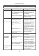


The light source is designed for this specific
application and can overheat if serviced by untrained
personnel. If any servicing is required, the product
should be returned to an authorized service facility
for examination or repair.
CAUTION
12
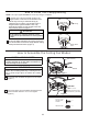
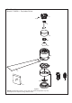
1. Remove the three screws from the light kit assembly.
and separate the support-cover switch cup from the light
kit housing. Retain the screws for later.
(Figure 1)
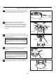
3. Connect the 2 single-pin connectors from the light
kit housing to the 2 single-pin connectors from the motor
assembly.
(Figure 3)
4. Assemble the light kit housing onto the support-cover
switch cup using the previously removed screws.
(Figure 4)
5. Secure the glass to light kit assembly by twisting in
a clockwise direction. Do not over-tighten.
(Figure 5)
2. Remove one of the four screws in the support
bracket at the bottom of the motor assembly.
Slightly loosen the remaining three screws. Assemble
the support-cover switch cup to the support bracket
using the three key slots in the support-cover switch
cup. Replace the fourth screw and securely tighten.
(Figure 2)
How to Assemble the Light Kit
Figure 1
Light Kit Assembly
Support-Cover Switch Cup
Light Kit Assembly
Glass
Support-Cover
Switch Cup
Figure 5
Figure 4
Figure 2
Motor
Assembly
Motor
Assembly
To reduce the risk of electric shock, disconnect the
electrical supply circult to the fan before installing
light kit.
CAUTION
Figure 3
Light Kit Housing
Light Kit Housing