
Installation Guide

How to Wire Your Ceiling Fan
10
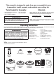
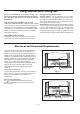
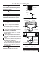
MAIN FUSE BOX
Figure 2
Figure 1
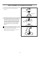
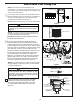
Figure 4
Green Wire
from Supply
(Ground)
White Wire
from Supply
White Wire
from Receiver
Green Wire
from Hanger
Bracket (Ground)
Green Wire
from Hanger
Ball (Ground)
Listed
Outlet Box
Household
Supply
Black Wire
from Supply
Black Wire
from Receiver
Receiver
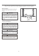
Figure 3
x 6WIRE
CONNECTORS
HARDWARE USED:
Bl
ue to
Light
Bl
ac
k t
o
M
o
t
or
W
hit
e
t
o
M
o
t
or
all
To avoid possible electrical shock, be sure electricity
is turned off at the main fuse box before wiring
(Figure 2).
WARNING
NOTE:
If you are not sure if the outlet box is
grounded, contact a licensed electrician for advice, as
it must be grounded for safe operation.
NOTE:
If you feel that you do not have enough electrical
wiring knowledge or experience, have your fan installed
by a licensed electrician.
Check to see that all connections are tight, including
ground, and that no bare wire is visible at the wire
connectors except for the ground wire. Do not
operate fan until the blades are in place. Noise and
motor damage could result.
WARNING
3. After connections have been made, turn leads
upward and carefully push leads into the outlet
box, with the white and green leads to one side
of the box and the black leads to the other side.
(Figure 4)
CAUTION: INCORRECT WIRE CONNECTION WILL
DAMAGE THIS RECEIVER.
2. Connect green wires from hanger bracket and
downrod to bare (ground) wire using wire connector.
Connect black wire from receiver unit marked “AC IN L”
to black supply wire using wire connector. Connect white
wire from receiver unit marked “AC IN N” to white supply
wire using wire connector. Connect white wire from
receiver unit marked “TO MOTOR N” to white wire from
fan using wire connector supplied with receiver unit.
Connect black wire from receiver unit marked “TO
MOTOR L” to black wire from fan using wire connector
supplied with receiver unit. Lastly, connect blue wire
from receiver unit to the blue fan light wire using wire
connector supplied with receiver unit. (Figure 3)
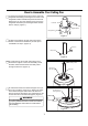
NOTE: The remote unit has 32 different code
combinations. To prevent possible interference from or to
other remote units, simply change the combination code
in the remote and receiver.
NOTE: Factory setting is all up. Do not use this position.
1. To set the code on receiver unit, slide dip switches to
the same positions as set on the remote. If complete the
receiver code setting process, put the rubber cover
(included) in the receiver unit. (Figure 1)
Dip Switch
ON DIP
1 2 3 4 5
Receiver Unit
Rubber Cover