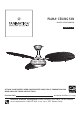
PALMA™ CEILING FAN MODEL #FP6258BNMW Español p. 18 ATTACH YOUR RECEIPT HERE AND REGISTER YOUR FAN AT FANIMATION.COM READ AND SAVE THESE INSTRUCTIONS Purchase Date Net Weight 24.69 . lbs (11.2 kgs) Questions, problems, missing parts? Before returning to your retailer, call our customer service department at 1-888-567-2055, 8 a.m.-5 p.m., EST, Monday-Friday.
Important Safety Instructions WARNING: To avoid fire, shock and serious personal injury, follow these instructions. 1. Read your owner’s manual and safety information before installing your new fan. Review the accompanying assembly diagrams. 2. Before servicing or cleaning unit, switch power off at service panel and lock service panel disconnecting means to prevent power from being switched on accidentally.
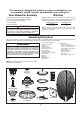
This manual is designed to make it as easy as possible for you to assemble, install, operate, and maintain your ceiling fan Tools Needed for Assembly Materials • One Phillips head screwdriver (supplied) • One 1/4˝ flat head screwdriver (supplied) • One hex wrench (not supplied) • One stepladder • One wire stripper Wiring outlet box and box connectors must be of type required by local code.
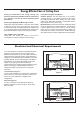
Energy Efficient Use of Ceiling Fans Ceiling fan performance and energy savings rely heavily on the proper installation and use of the ceiling fan. Here are a few tips to ensure efficient product performance. Choosing the Appropriate Mounting Location Ceiling fans should be installed, or mounted, in the middle of the room and at least 7 feet above the floor and 18 inches from the walls. If ceiling height allows, install the fan 8 - 9 feet above the floor for optimal airflow.
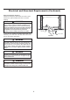
Electrical and Structural Requirements (Continued) Deep box with brace (Figure 3) Paired with a deep box, this hanger is meant to span between two joists and takes the place of wooden blocking. CEILING JOIST WARNING To reduce the risk of fire, electric shock, or personal injury, mount to outlet box marked acceptable for fan support of 15.9 kg (35 lbs) or less and use mounting screws provided with the outlet box.
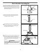
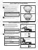
How to Assemble Your Ceiling Fan 1. Remove the hanger ball portion from the downrod/ hanger ball assembly by loosening the set screw in the hanger ball until the ball falls freely down the downrod. Remove the pin from the downrod, then remove the hanger ball. Retain the pin and hanger ball for reinstallation in Step 6. (Figure 1) Pin Downrod Set Screw Hanger Ball Figure 1 2. Remove the hairpin clip and clevis pin from the bottom of the downrod. Retain the pin and clip for reinstallation in Step 4.
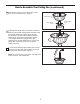
How to Assemble Your Ceiling Fan (continued) 5. Route wires through motor coupling cover, canopy screw cover and ceiling canopy. (Figure 5) Ceiling Canopy Motor Coupling Cover Canopy Screw Cover Figure 5 6. Reinstall the hanger ball on the downrod as follows. Route the black, white and blue wires and safety cable through the hanger ball. Position the pin through the two holes in the downrod and align the hanger ball so the pin is captured in the groove in the top of the hanger ball.
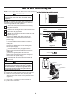
How to Hang Your Ceiling Fan WARNING To avoid possible electrical shock, be sure electricity is turned off at the main fuse box before hanging. (Figure 1) NOTE: If you are not sure if the outlet box is grounded, contact a licensed electrician for advice, as it must be grounded for safe operation. MAIN FUSE BOX Figure 1 WARNING The fan must be hung with at least 7´ of clearance from floor to blades.
How to Wire Your Ceiling Fan NOTE: If fan or supply wires are different colors than indicated, ha WARNING To avoid possible electrical shock, be sure electricity is turned off at the main fuse box before wiring. (Figure 1). MAIN FUSE BOX NOTE: If you are not sure if the outlet box is grounded, contact a licensed electrician for advice, as it must be grounded for safe operation. Figure 1 1. Disconnect the power and remove the existing wall plate and switch.
How to Install Your Canopy Housing NOTE: This step is applicable after the neccessary wiring is completed. 1. Remove one of the two shoulder screws in the hanger bracket. Loosen the second shoulder screw without fully removing it. Assemble canopy by rotating key slot in canopy over shoulder screw in hanger bracket. Tighten shoulder screw. Fully assemble and tighten second shoulder screw that was previously removed.
How to Assemble Your Light Kit Assembly or Cap 1. Remove one of the three screws in the adaptor plate at the bottom of the motor assembly. Slightly loosen the remaining two screws. (Figure 1) Motor Assembly Figure 1 2. Assemble the housing assembly to the adaptor plate of the motor assembly using the two key slots in the housing assembly. Replace the third screw and secure all three screws. (Figure 2) Housing Assembly Motor Assembly Figure 2 3.
How to Assemble Your Light Kit Assembly or Cap (continued) 6. Securely attach the light screw cover assembly over the screws in the housing assembly utilizing the key slot twist-lock feature. (Figure 6) LED Assembly Housing Assembly Steel Cap Light Screw Cover Assembly Housing Assembly Light Screw Cover Assembly Figure 6 How to Operate Your Ceiling Fan 1. Restore electrical power to the outlet box by turning the electricity on at the main fuse box.
Maintenance 1. Periodic cleaning of your new ceiling fan is the only maintenance that is needed. When cleaning, use only a soft brush or lint free cloth to avoid scratching the finish. Abrasive cleaning agents are not required and should be avoided to prevent damage to finish. CAUTION Do not use solvents when cleaning your ceiling fan. It could damage the motor or the blades and create the possibility of electrical shock.
Parts List Model #FP6258BNMW Ref.
PALMA™ Model FP6258BNMW Exploded-View Illustration 1 2 3 4 5 9 8 6 7 11 10 13 12 NOTE: The illustration shown is not to scale or its actual parts configuration may var.
Trouble Shooting WARNING For your own safety turn off power at fuse box or circuit breaker before trouble shooting your fan. Trouble Probable Cause 1. Fuse or circuit breaker blown. 1.FAN WILL NOT START 2. Loose power line connections to the fan, or loose switch wire connections in the switch housing. 3. Reversing switch in neutral position. 1. Blades not attached to fan. 2. Loose screws in motor housing. 2.FAN SOUNDS NOISY 3. Screws securing fan blade holders to motor flywheel are loose. 4.
10983 Bennett Parkway Zionsville, IN 46077 Phone: 888-567-2055 Outside U.S.: 317-733-4113 FAX: 866-482-5215 FANIMATION.COM 2017/01 V.