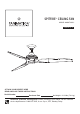
SPITFIRE ™ CEILING FAN MODEL #MA6721B** Español p. 17 ATTACH YOUR RECEIPT HERE READ AND SAVE THESE INSTRUCTIONS Serial Number Purchase Date Net Weight : 16.34 lbs (7.41 kg) Questions, problems, missing parts? Before returning to your retailer, call our customer service department at 1-888-567-2055, 8 a.m.-5 p.m., EST, Monday-Friday.
Important Safety Instructions WARNING: To avoid fire, shock and serious personal injury, follow these instructions. 1. Read your owner’s manual and safety information before installing your new fan. Review the accompanying assembly diagrams. 2. Before servicing or cleaning unit, switch power off at service panel and lock service panel disconnecting means to prevent power from being switched on accidentally.
Table of Contents Unpacking Instructions. . . . . . . . . . . . . . . . . . . . . . . . . . . 4 Energy Efficient Use of Ceiling Fans . . . . . . . . . . . . . . . . 5 Electrical and Structural Requirements. . . . . . . . . . . . . . 5 How to Assemble Your Ceiling Fan. . . . . . . . . . . . . . . . . 6 How to Hang Your Ceiling Fan . . . . . . . . . . . . . . . . . . . . . 7 How to Wire Your Ceiling Fan . . . . . . . . . . . . . . . . . . . . . . 8 Installing the Canopy Housing . . . . . . . . . . . . . . . .
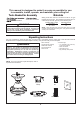
This manual is designed to make it as easy as possible for you to assemble, install, operate, and maintain your ceiling fan Tools Needed for Assembly Materials Wiring outlet box and box connectors must be of type required by local code. The minimum wire would be a 3conductor (2-wire with ground) of the following size: Four wire connectors blade screwdriver WARNING Before assembling your ceiling fan, refer to section on proper method of wiring your fan (page 8).
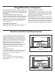
Energy Efficient Use of Ceiling Fans Ceiling fan performance and energy savings rely heavily on the proper installation and use of the ceiling fan. Here are a few tips to ensure efficient product performance. Choosing the Appropriate Mounting Location Ceiling fans should be installed, or mounted, in the middle of the room and at least 7 feet from floor to the blade and 18 inches from wall to the blade. If ceiling height allows, install the fan 8 - 9 feet from floor to the blade for optimal airflow.
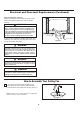
Electrical and Structural Requirements (Continued) Deep box with brace (Figure 3) Paired with a deep box, this hanger is meant to span between two joists and takes the place of wooden blocking. CEILING JOIST WARNING To reduce the risk of fire, electric shock, or personal injury, mount to outlet box marked acceptable for fan support of 15.9 kg (35 lbs) or less and use mounting screws provided with the outlet box.
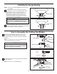
How to Hang Your Ceiling Fan WARNING To avoid possible electrical shock, be sure electricity is turned off at the main fuse box before hanging. (Figure 1) NOTE: If you are not sure if the outlet box is grounded, contact a licensed electrician for advice, as it must be grounded for safe operation. MAIN FUSE BOX Figure 1 WARNING The fan must be hung with at least 7´ of clearance from floor to blades.
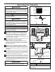
How to Wire Your Ceiling Fan NOTE: The remote unit has 32 different code combinations. To prevent possible interference from or to other remote units, simply change the combination code in the remote and receiver. Receiver Unit ON 1. To set the code on receiver unit, slide dip switches to the same positions as set on the remote. (Figure 1) 1 DIP 2 3 4 5 Dip Switch NOTE: Factory setting is all up. Do not use this position.
Installing the Canopy Housing NOTE: This step is applicable after the neccessary wiring is completed. 1. Remove one of the two shoulder screws in the hanger bracket. Loosen the second shoulder screw without fully removing it. Assemble canopy by rotating key slot in canopy over shoulder screw in hanger bracket. Tighten shoulder screw. Fully assemble and tighten second shoulder screw that was previously removed.
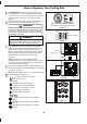
How to Operate Your Ceiling Fan 1. IMPORTANT: Using a full range dimmer switch (not included) to control fan speed will damage the fan. To reduce the risk of fire or electrical shock, do not use a full range dimmer switch to control the fan speed. (Figure 1) 2. Restore electrical power to the outlet box by turning the electricity on at the main fuse box.
How to Operate Your Ceiling Fan (Continued) 6. If airflow is desired in the opposite direction, turn the fan off and wait for the blades to stop turning. Then slide the reverse switch on top of motor assembly to the opposite position and turn fan on again. (Figure 6) Reversing Switch Reverse Switch Information Season Summer Winter Rotation Direction Counter-Clockwise Clockwise Switch Position Left Right Figure 6 How to Install Your Remote Control 1.
Parts List Model #MA6721B** Ref.
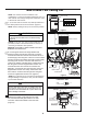
MA6721B** Exploded-View Illustration 1 2a 2b 2c 2 2d 2e 3 4 5 6 NOTE: The illustration shown is not to scale or its actual parts configuration may var.
Optional Light Kit 1 Light Kit Assembly LK6721B** Optional Fan Blade 1 Blade Set B6720** 2 Blade Set B6720-48** NOTE: The illustration shown is not to scale or its actual configuration may vary. Before discarding packaging materials, be certain all parts have been removed How To Order Parts When ordering repair parts, always give the following information: • Part Number • Part Description • Fan Model Number Contact your retail store for repair parts.
Trouble Shooting ! WARNING For your own safety, turn off power at fuse box or circuit breaker before trouble shooting your fan. Some suggested remedies require the attention of a licensed electrician. Trouble Probable Cause 1. Fuse or circuit breaker blown. 1.FAN WILL NOT START 2.FAN SOUNDS NOISY Suggested Remedy 2. Loose power line connections to the fan, or loose switch wire connections in the switch housing. 1. Check main and branch circuit fuses or circuit breakers. 2.
10983 Bennett Parkway Zionsville, IN 46077 Phone: 888-567-2055 Outside U.S.: 317-733-4113 FAX: 866-482-5215 FANIMATION.COM 2019/01V.
VENTILADOR DE TECHO SPITFIRE™ MODELO #MA6721B** ADJUNTE SU RECIBO AQUÍ Y REGISTRE SU VENTILADOR EN FANIMATION.COM LEA Y GUARDE ESTAS INSTRUCCIONES Número de serie Fecha de compra Peso neto 7.41 kg (16.34 lbs) Preguntas, problemas, piezas faltantes? Antes de volver a la tienda, llame a nuestro Departamento de Servicio al Cliente al 1-888-567-2055, 8 a.m. - 5 pm, hora del Este, de lunes - viernes.
Instrucciones de seguridad importantes ADVERTENCIA: Siga estas instrucciones para prevenir incendios, descargas eléctricas y lesiones personales graves. 1. Lea el manual del propietario y la información de seguridad antes de instalar su nuevo ventilador. Observe los diagramas de ensamblaje adjuntos. 2. Antes de llevar a cabo el mantenimiento o la limpieza de la unidad, desconecte la electricidad en el panel de servicio y bloquee los medios de desconexión del mismo para evitar que se active accidentalmente.
GARANTÍA LIMITADA DE POR VIDA Se extiende al comprador original de un ventilador Fanimation 1. GARANTÍA LIMITADA DE POR VIDA DEL MOTOR - Si se produjera una falla en alguna de las partes del motor de su ventilador debido a un defecto en los materiales o en la fabricación durante el tiempo de vida del comprador original, Fanimation proporcionará la pieza de repuesto sin cargo una vez que el ventilador defectuoso sea devuelto a nuestro centro de servicios nacional. Se requiere comprobante de venta.
Este manual está diseñado para facilitar al máximo el ensamblaje, la instalación, el funcionamiento y el mantenimiento de su ventilador de techo. Herramientas necesarias para el ensamblaje Materiales é L ñ • Cuatro conectores de cables x ñ : W 14 12 ADVERTENCIA Antes de ensamblar el ventilador de techo, consulte la sección sobre el método correcto de instalación eléctrica del ventilador (página 25).
Uso eficiente de la energía en ventiladores de techo El nivel de rendimiento y ahorro de energía de los ventiladores de techo dependen de su correcta instalación yuso.Acontinuaciónlepresentamosalgunassugerencias para asegurar un rendimiento eficiente del producto. Uso del ventilador de techo todo el año En verano: Use el ventilador de techo en sentido contrario a las agujas del reloj. El flujo de aire que produce el ventilador creará un efecto frío del aire que lo refrescará más.
Requisitos eléctricos y estructurales (cont.) Uso del soporte (Figura 3) Conectado a una caja de distribución eléctrica, este colgador sirve para abarcar el espacio entre dos vigas y ocupar el lugar de bloqueo de la madera. Vigas del techo ADVERTENCIA Para reducir el riesgo de incendios, descargas eléctricas o lesiones personales, fije el ventilador a la caja de distribución eléctrica marcada como aceptable para soporte de ventilador de 15,88kg (35lb).
Cómo ensamblar el ventilador de techo 15, 2 22, 4 cm 86 cm a 1. Corte el exceso de cable aproximadamente de 15 a 23 cm (6 a 9 pulgadas) por encima de la parte superior del barral. Pele 1,2 cm (½ ) del aislamiento en cada extremo del cable. (Figura 1) NOTA: Se deben revisar todos los tornillos de fijación y volver a ajustarlos cuando sea necesario antes de realizar la instalación.
Cómo colgar el ventilador de techo (cont.) 2. Fije adecuadamente el soporte colgante a la caja de empalme del techo que sea aceptable para el soporte del techo. NOTA: el cable de soporte para techo no se puede asegurar solamente a la caja de conexiones; se debe asegurar directamente a la viga de techo o miembro ATTENTION Do not connect fan blades until the fan is completely installed. Hanging fan with blades connected may result in damage to the fan blades. ADVERTENCIA y la arandela plana. (Figura 3) 3.
Cómo realizar la instalación eléctrica del ventilador de techo NOTA: El mando a distancia incluido en este ventilador tiene 32 combinaciones diferentes de códigos. Para evitar posibles interferencias desde o hacia otros mandos a distancia, modifique el código de combinación de su transmisor y receptor. Unidad del receptor ON 1 1. Para configurar el código de unidad del receptor. Deslice los interruptores de código a las mismas posiciones que en el transmisor.
Cómo realizar la instalación eléctrica del ventilador de techo (cont.) 3. Una vez realizadas las conexiones, gire los conductores hacia arriba y, con cuidado, colóquelos dentro de la caja de salida; con los conductores blancos y verdes hacia un lado y los conductores negros hacia el otro.
Cómo ensamblar las aspas del ventilador de techo 1. Asegure las tres palas usando los 20 tornillos de ¼˝ con arandelas planas en la placa de las palas a través de los orificios ubicados en la parte inferior del motor. (Figura 1) Aspa (no está incluido) Motor NOTA: Encontrará que la pala del ventilador viene empaquetada en su propio envoltorio de cartón la bolsa del hardware vienen en la caja del ventilador.
Cómo utilizar su ventilador de techo (cont.) 2. Restaure la fuente de alimentación de la toma de corriente enciendo la electricidad del fusible principal. (Figura 2) PRINCIPAL CAJA DE FUSIBLES ADVERTENCIA Compruebe que todas las conexiones realizadas correctamente, incluyendo la toma de tierra, y que no se visualizan ningún cable pelado en los conectores de cables, con la excepción del cable de toma de tierra.
Cómo utilizar su ventilador de techo (cont.) 6. Si desea que el flujo de aire se desplace en la dirección opuesta, apague el ventilador y espere a que las aspas se detengan. Luego deslice el conmutador inversor a la posición contraria y vuelva a encender el ventilador.
Lista de piezas ModeloN.°MA6721B** N.° de Ref. Descripción Pieza N.
MA6721B** Ilustración del despiece 1 2a 2b 2c 2 2d 2e 3 4 5 6 Figura 1 NOTA: La ilustración que se muestra no está hecha a escala y su c 31 guración real y/o terminación puede variar
Kit de iluminación opcional 1 Ensamble de Kit de iluminación LK6721B** Paquete de las ocho palas opcional 1 Juego de aspa B6720** 2 Juego de aspa B6720-48** NOTA: la ilustración que se muestra no está hecha a escala y su configuración real puede variar.
Solución de problemas ▲ADVERTENCIA Para su propia seguridad, desconecte la electricidad de la caja de fusibles o disyuntor antes de solucionar problemas en su ventilador. ▲AVERTISSEMENT Pour votre sécurité, placez le coffret à fusibles ou le disjoncteur hors tension avant de tenter d’identifier tout problème pouvant affecter votre ventilateur. Problema 1. EL VENTILADOR NO ARRANCA Causa posible Solución sugerida 1. El fusible o el disyuntor están fundidos. 1.
10983 Bennett Parkway Zionsville, IN 46077 Llame sin cargo al (888) 567-2055 FAX (866) 482-5215 Desde fuera de los EE.UU., llame al (317) 733-4113 Visite nuestro sitio Web en www.fanimation.com 2019/01 V.