The Benito ™ Ceiling Fan Net Weight 9.3 kg. (20.5 lbs.) Model No.
Important Safety Instructions WARNING: To avoid fire, shock and serious personal injury, follow these instructions. 1. Read your owner’s manual and safety information before installing your new fan. Review the accompanying assembly diagrams. 2. Before servicing or cleaning unit, switch power off at service panel and lock service panel disconnecting means to prevent power from being switched on accidentally.
LIMITED LIFETIME WARRANTY Extends to the original purchaser of a Fanimation Fan 5. This warranty is void and does not apply to damage from improper installation, neglect, accident, misuse, exposure to extremes of heat or humidity, or as a result of any modification to the original product. 6. All costs of removal and reinstallation of the fan are the sole responsibility of the owner of the fan and not the store that sold the fan or Fanimation. 7.
This manual is designed to make it as easy as possible for you to assemble, Install, operate and maintain your ceiling fan Materials Tools Needed for Assembly • One Phillips head screwdriver • One stepladder • Three wire connectors (supplied) Wiring outlet box and box connectors must be of type required by the local code. The minimum wire would be a 3-conductor (2-wire with ground) of the following size: • One wire stripper • One 1/4” blade screwdriver Installed Wire Length Up to 50 ft. 50-100 ft.
Energy Efficient Use of Ceiling Fans Using the Ceiling Fan Year Round Summer Season: Use the ceiling fan in the counterclockwise direction. The airflow produced by the ceiling fan creates a wind-chill effect, making you “feel” cooler. Select a fan speed that provides a comfortable breeze, lower speeds consume less energy. Ceiling fan performance and energy savings rely heavily on the proper installation and use of the ceiling fan. Here are a few tips to ensure efficient product performance.
How to Assemble Your Ceiling Fan 1. Remove the hanger ball portion from the downrod/hangerball assembly by loosening the set screw in the hanger ball until the ball falls freely down the downrod. Remove the pin from the downrod, then remove the hanger ball. Retain the pin and hanger ball for reinstallation in Step 6 (Figure 1). PIN DOWNROD SET SCREW HANGER BALL Figure 1 2. Remove the hairpin clip and clevis pin from the bottom of the downrod.
How to Assemble Your Ceiling Fan (continued) 6. Reinstall the hanger ball on the downrod as follows.Route the three 80-inch wires through the hanger ball. Position the pin through the two holes in the downrod and align the hanger ball so the pin is captured in the groove in the top of the hanger ball. Pull the hanger ball up tight against the pin. Securely tighten the set screw in the hanger ball. A loose set screw could create fan wobble (Figure 6).
How to Hang Your Ceiling Fan (continued) 2. Carefully lift the fan and seat the downrod/hanger ball assembly on the hanger bracket that was just attached to the outlet box. Be sure the groove in the ball is lined up with tab on the hanger bracket (Figure 3). OUTLET BOX WARNING Failure to seat tab in groove could cause damage to electrical wires and possible shock or fire hazard. WARNING Figure 3 To avoid possible shock, do not pinch wires between the hanger ball assembly and the hanger bracket.
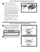
How to Wire Your Ceiling Fan (Continued) 3. LEARN MODE PROCESS: (Figure 4) • Control and receiver have been factory programmed. If replacing the ransmtitter or receiver, the learn mode process will need to be used. • After installing the unit and restoring power to your fan, open the battery cover (with battery, DC12V/A23 1pc, installed) and press and hold the ”LEARNING BUTTON” 1~3 seconds with a ballpoint pen or similar object.
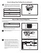
How to Assemble the Blades and Light Kit 1. Position the blade over the blade holder with threaded posts showing. Make sure the bottom edge of the blade is fully seated against the blade arm. With a Phillips screwdriver, tighten 3/16-24 x 7.5 mm washer head screws and fiber washers to secure the blade to the blade arm (Figure 1). 3/16-24 x 7.5 mm WASHER HEAD SCREW AND FIBER WASHER (3 each per blade) CAUTION BLADE Do not connect fan blades until the fan is completely installed.
How to Assemble the Blades and Light Kit (continued) 4. Connect the 2-pin connector from the socket plate assembly to 2-pin connector from motor assembly (Figure 4). MOTOR ASSEMBLY 2-PIN CONNECTOR SOCKET PLATE 2-PIN CONNECTOR Figure 4 5. Remove one of the three screws in the socket plate assembly. Slightly loosen the remaining two screws. Assemle the socket plate assembly to the adapter plate assembly using the two key slots. Replace the third screw and securely tighten all three screws (Figure 5).
How to Operate Your Ceiling Fan 1. Restore electrical power to the outlet box by turning the electricity on at the main fuse box (Figure 1). WARNING MAIN FUSE BOX Check to see that all connections are tight, including ground, and that no bare wire is visible at the wire connectors, except for the ground wire. Do not operate fan until the blades are in place. Noise and fan damage could result. Figure 1 2.
Trouble Shooting ! WARNING For your own safety turn off power at fuse box or circuit breaker before trouble shooting your fan. Trouble Probable Cause 1. Fuse or circuit breaker blown. 1.FAN WILL NOT START 2. Loose power line connections to the fan, or loose switch wire connections in the switch housing. 3. Reversing switch in neutral position. 4. Dead battery in remote control. 1. Blades not attached to fan. 2. Loose screws in motor housing. 2.FAN SOUNDS NOISY 3.
Parts List Model No. FP8003**-220 Reference # 1 2 3 4 5 6 7 8 Description Part # 9 10 11 Hanger Bracket Assembly w/Screws Ball - Downrod Assembly (4.
FP8003**-220 Exploded-View 1 14 2 3 13 15 4 5 6 11 10 7 9 8 12 NOTE: The illustration shown is not to scale or its actual configurations may vary.
10983 Bennett Parkway Zionsville, IN 46077 Toll Free (888) 567-2055 FAX (866) 482-5215 Outside U.S. call (317) 733-4113 Fanimation Visit Our Website www.fanimation.com Copyright 2013 2013/06 V.
The Benito ™ Ventilador de techo Versión Peso neto 20.5 lb (9.3 kg) Modelo N.
Instrucciones de seguridad importantes ADVERTENCIA: Siga estas instrucciones para prevenir incendios, descargas eléctricas y lesiones personales graves. 1. Lea el manual del propietario y la información de seguridad antes de instalar su nuevo ventilador. Observe los diagramas de ensamblaje adjuntos. 2.
GARANTÍA LIMITADA DE POR VIDA Se extiende al comprador original de un ventilador Fanimation 6. Todos los gastos de remoción y reinstalación del ventilador son responsabilidad exclusiva del propietario, y no de la tienda que vendió el ventilador ni de Fanimation. 7. Fanimation se reserva el derecho de modificar o discontinuar un producto en cualquier momento, o sustituir cualquier pieza según lo establecido por esta garantía. 8.
Este manual está diseñado para facilitar al máximo el ensamblaje, la instalación, el funcionamiento y el mantenimiento de su ventilador de techo. Herramientas necesarias para el ensamblaje • Destornillador Phillips • Escalera de tijera • Destornillador de ¼˝ Materiales La caja de distribución eléctrica y los conectores de la caja deben ser del tipo requerido por el código local.
Uso eficiente de la energía en ventiladores de techo Uso del ventilador de techo todo el año El nivel de rendimiento y ahorro de energía de los ventiladores de techo dependen de su correcta instalación yuso.Acontinuaciónlepresentamosalgunassugerencias para asegurar un rendimiento eficiente del producto. En verano: Use el ventilador de techo en sentido contrario a las agujas del reloj. El flujo de aire que produce el ventilador creará un efecto frío del aire que lo refrescará más.
Cómo ensamblar el ventilador de techo 1. Extraiga la pieza de la bola colgante de la unidad de la bola colgante / varilla aflojando el tornillo de presión de la bola colgante hasta que la bola se libere de la varilla. Retire el pasador del barral y luego extraiga la semiesfera. Conserve el pasador y la semiesfera para su reinstalación en el Paso 6. (Figura 1) Pasador Bola para colgar Tornillo de fijación Ranura de la bola colgante Figura 1 2 Retire .
Cómo ensamblar el ventilador de techo (cont.) 6. Vuelva a colocar la semiesfera en el barral como se indica a continuación. Pase los tres cables de 2.03 m (80˝) a través de la semiesfera. Pase el pasador a través de los dos orificios en el barral y alinee la semiesfera de modo que el pasador quede atrapado en la ranura de la parte superior de la misma. Empuje la semiesfera hacia arriba, bien ajustada contra el pasador. Ajuste firmemente el tornillo de fijación en la semiesfera.
Cómo colgar el ventilador de techo (cont.) 2. Levante cuidadosamente el ventilador y coloque el ensamble de la bola para colgar/varilla en la abrazadera para colgar que acaba de fijar a la caja de salida. Asegúrese de que la ranura de la bola esté alineada con la lengüeta de la abrazadera para colgar. (Figura 3) Caja de salida ADVERTENCIA Si no coloca la lengüeta en la ranura, podrían dañarse los cables eléctricos y podrían ocurrir incendios o descargas eléctricas.
Cómo realizar la instalación eléctrica del ventilador de techo (cont.) 3. PROCESO DEL MODO APRENDIZAJE: (Figura 4) • El mando y el receptor vienen programados de fábrica. Si sustituyera el transmisor o el receptor, tendrá que aplicar el proceso del modo aprendizaje. • Cuando haya instalado la unidad y la fuente de restauración en su ventilador, abra la carcasa de la pila (con la pila, CD12V / A23, instalada) y mantenga pulsado el “botón de aprendizaje” durante 1-3 segundos con un bolígrafo u objeto similar.
Cómo ensamblar los Blades y kit de luces 1. Coloque el aspa sobre el soporte de aspas con los pilotes roscados a la vista. Asegúrese de que la parte inferior del aspa se encuentre bien apoyada sobre el soporte. Con un destornillador Phillips, fije los tornillos con cabeza de arandela de 3/16-24 x 7.5 mm para asegurar la placa en el brazo de sujeción de las palas. (Figura 1) arandela de la cabeza del tornillo de 3/16-24 x 7.
Cómo ensamblar los Blades y kit de luz (cont.) 4. Instale el conector de 2 clavijas desde la placa de conexión a la unidad del motor. (Figura 4) El conjunto del motor Conector de 2 pines Toma de la placa del conector de 2 clavijas Figura 4 5. Extraiga uno de los tres tornillos de la unidad de la placa. Afloje levemente los otros dos tornillos. Instale la placa de conexión en la unidad de la placa de luz utilizando las dos ranuras principales.
Cómo utilizar su ventilador de techo 1. Restaure la fuente de alimentación de la toma de corriente enciendo la electricidad del fusible principal. (Figura 1) ADVERTENCIA PRINCIPAL CAJA DE FUSIBLES Compruebe que todas las conexiones realizadas correctamente, incluyendo la toma de tierra, y que no se visualizan ningún cable pelado en los conectores de cables, con la excepción del cable de toma de tierra.
Solución de problemas ▲ADVERTENCIA Para su propia seguridad, desconecte la electricidad de la caja de fusibles o disyuntor antes de solucionar problemas en su ventilador. Problema 1. EL VENTILADOR NO ARRANCA Causa posible Solución sugerida 1. El fusible o el disyuntor están fundidos. 1. Controle los fusibles del circuito principal y derivado o los disyuntores. 2. Las conexiones eléctricas del ventilador o del interruptor en la caja del interruptor están flojas. 2.
Lista de piezas Modelos N.° FP8003**-220 N.° de Ref. Pieza # N.° Descripción Unidad del soporte de suspensión Unidad del barral/de la semiesfera (4.
FP8003**-220 1 Despiece 14 2 3 13 15 4 5 6 11 10 7 9 8 12 NOTA: 31
10983 Bennett Parkway Zionsville, IN 46077 Llame sin cargo al (888) 567-2055 FAX (866) 482-5215 Desde fuera de los EE.UU., llame al (317) 733-4113 Visite nuestro sitio Web en www.fanimation.com Copyright 2013 2013/06 V0.