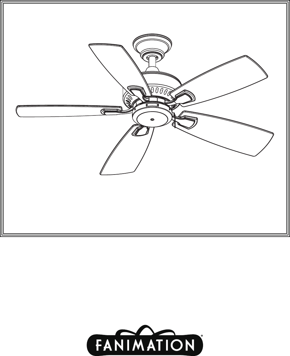
™ The Cancun 42” Ceiling Fans Net Weight 6.97 kg (15.37 lbs) Model Nos.
Important Safety Instructions WARNING: To avoid fire, shock and serious personal injury, follow these instructions. 1. 2. 3. 4. 5. Read your owner’s manual and safety information before installing your new fan. Review the accompanying assembly diagrams. Before servicing or cleaning unit, switch power off at service panel and lock service panel disconnecting means to prevent power from being switched on accidentally.
This Manual is Designed to Make it as Easy as Possible for You to Assemble, Install, Operate, and Maintain Your Ceiling Fan Tools Needed for Assembly • One Phillips head screwdriver • One stepladder • One ¼˝ blade screwdriver Materials • One wire stripper • Three wire connectors (supplied) Wiring outlet box and box connectors must be of type required by local code. The minimum wire would be a 3conductor (2-wire with ground) of the following size: Installed Wire Length WARNING Up to 50 ft. 50 - 100 ft.
Energy Efficient Use of Ceiling Fans Ceiling fan performance and energy savings rely heavily on the proper installation and use of the ceiling fan. Here are a few tips to ensure efficient product performance. Using the Ceiling Fan Year Round Summer Season: Use the ceiling fan in the counterclockwise direction. The airflow produced by the ceiling fan creates a wind-chill effect, making you “feel” cooler. Select a fan speed that provides a comfortable breeze, lower speeds consume less energy.
How to Assemble Your Ceiling Fan (Downrod) 1. Remove the hanger ball portion from the downrod/ hanger ball assembly by loosening the set screw in the hanger ball until the ball falls freely down the downrod. Remove the pin from the downrod, then remove the hanger ball. Retain the pin and hanger ball for reinstallation in Step 5. (Figure 1) Pin Downrod Set Screw Hanger Ball Figure 1 2. Loosen the two set screws in the downrod support of the motor assembly.
How to Assemble Your Ceiling Fan (Downrod)-Cont’d 6. Cut off excess lead wire approximately 6 to 9 inches above top of the top of the downrod. Strip insulation off 1/2 inch from the end of each lead wire. (Figure 6) NOTE: All set screws must be checked, and retightened where necessary, before installation. Figure 6 How to Assemble Your Ceiling Fan (Close to Ceiling) 1. Remove the three motor coupling screws from your fan and save for step 3.
How to Assemble Your Ceiling Fan (Close to Ceiling)-Cont’d OUTLET BOX 4. Lift your fan motor assembly and hang it from the hanger bracket hook through one of the two screw holes in the canopy lip. Do not use the grooved slots. Connect your fan’s wiring according to how to wire your ceiling fan in page 9 owner’s manual. (Figure 5) HOOK HANGER BRACKET MOTOR ASSEMBLY Figure 5 5. Completely remove one of each screw where on the flap of hanger bracket, and keep for reinstall in step 7.
How to Hang Your Ceiling Fan with Downrod WARNING To avoid possible fire or shock, be sure electricity is turned off at the main fuse box before hanging. (Figure 7) MAIN FUSE BOX NOTE: If you are not sure if the outlet box is grounded, contact a licensed electrician for advise, as it must be grounded for safe operation. Figure 7 Ceiling WARNING The fan must be hung with at least 7’ of clearance from floor to blades. (Figure 8) No less than 7 ft Floor Figure 8 1.
How to Wire Your Ceiling Fan (Cont’d) 1. Connect the green grounding lead from the hanger ball and the green grounding lead from the hanger bracket to the supply grounding conductor (this may be a bare wire or wire with green colored insulation). Securely connect wires with wire connectors supplied. (Figure 12) BLACK FAN WIRE BLACK LISTED OUTLET BOX GREEN WIRE (GROUND) HOUSEHOLD SUPPLY GREEN WIRE (GROUND) FROM HANGER BRACKET 2.
Installing the Canopy Housing (continued) 4. Push the Canopy Trim Ring up to conceal the screws of Ceiling Canopy. (Figure 17) Canopy Trim Ring Figure 17 How to Assemble the Blades 1. Remove and discard the five rubber motor stops from the motor assembly by removing the screws. (Figure 18) CAUTION Do not connect fan blades until the fan is completely installed. Installing the fan with blades assembled may result in damage to the fan blades. 2.
Housing/Switch Cup Assembly 1. Disassemble the housing switch cup assembly by removing three screws. (Figure 21) Switch Cup Assembly Figure 21 2. Remove one of the three screws in the support bracket. Slightly loosen the remaining two screws. Assemble the adapter assembly to the housing support bracket using the two key slots in the switch cup assembly. Replace the third screw and securely tighten all three screws. (Figure 22) Screws(3) Switch Cup Assembly Figure 22 3.
Parts List Models FP8042** Ref.
FP8042** Exploded-View 1 2 3 4 5 6 7 8 11 9 10 NOTE: The illustration shown is not to scale or its actual configuration may vary.
Trouble Shooting WARNING For your own safety turn off power at fuse box or circuit breaker before trouble shooting your fan. Trouble 1. FAN WILL NOT START Probable Cause Suggested Remedy 1. Fuse or circuit breaker blown. 1. Check main and branch circuit fuses or circuit breakers. 2. Loose power line connections to the fan, or loose switch wire connections in the switch housing. 2. Check line wire connections to fan and switch wire connections in the switch housings.
Copyright 2010 Fanimation 10983 Bennett Parkway Zionsville, IN 46077 Toll Free (888) 567-2055 FAX (866) 482-5215 Outside U.S. call (317) 733-4113 Visit Our Website @ www.fanimation.
™ The Cancun 42” Ventilador de techo Peso neto 6,97 kg (15,37 lb) Modelo N.
Instrucciones de seguridad importantes ADVERTENCIA: Siga estas instrucciones para prevenir incendios, descargas eléctricas y lesiones personales graves. 1. Lea el manual del propietario y la información de seguridad antes de instalar su nuevo ventilador. Observe los diagramas de ensamblaje adjuntos. 2. Antes de llevar a cabo el mantenimiento o la limpieza de la unidad, desconecte la electricidad en el panel de servicio y bloquee los medios de desconexión del mismo para evitar que se active accidentalmente.
Este manual está diseñado para facilitar al máximo el ensamblaje, la instalación, el funcionamiento y el mantenimiento de su ventilador de techo. Herramientas necesarias para el ensamblaje • Destornillador Phillips • Escalera de tijera • Destornillador de ¼˝ • Pelacables • Tres conectores de cables (incluidos) ADVERTENCIA Materiales La caja de distribución eléctrica y los conectores de la caja deben ser del tipo requerido por el código local.
Uso eficiente de la energía en ventiladores de techo El nivel de rendimiento y ahorro de energía de los ventiladores de techo dependen de su correcta instalación y uso. A continuación le presentamos algunas sugerencias para asegurar un rendimiento eficiente del producto. Uso del ventilador de techo todo el año En verano: Use el ventilador de techo en sentido contrario a las agujas del reloj. El flujo de aire que produce el ventilador creará un efecto frío del aire que lo refrescará más.
Cómo instalar su ventilador de techo (Barra Vertical) 1. Extraiga la parte de la bola de suspensión de la unidad de bola de suspensión/barra vertical aflojando los tornillos ubicados en la bola hasta que ésta se libere de la barra vertical. Extraiga el enganche de la barra vertical y extraiga la bola de suspensión. Conserve la bola de suspensión y el enganche para su reinstalación en el paso 5. (Figura 1) Pasador Barra Vertical Tornillo de fijación Bola para colgar Figura 1 2.
Cómo instalar su ventilador de techo (Barra Vertical)-Cont. 15, 2 22, 4 cm 86 cm a 6. Corte el exceso de cable aproximadamente de 15 a 23 cm (6 a 9 pulgadas) por encima de la parte superior del barral. Pele 1,2 cm (½˝) del aislamiento en cada extremo del cable. (Figura 6) NOTA: Se deben revisar todos los tornillos de fijación y volver a ajustarlos cuando sea necesario antes de realizar la instalación. Figura 6 Cómo ensamblar el ventilador de techo (Cerca del techo) 1.
Cómo ensamblar el ventilador de techo (Cerca del techo)-Cont. 4. Levante la unidad del motor de su ventilador y cuélguela del enganche de soporte del gancho a través de uno de los dos orificios de tornillos ubicados en la tapa de la cubierta. No utilice las ranuras con muescas. Conecte el cableado de su ventilador según las indicaciones facilitadas en la sección Cómo realizar el cableado de su ventilador de techo de la página 9 del manual del usuario.
Cómo colgar su ventilador de techo con la barra vertical ADVERTENCIA Para evitar una posible descarga eléctrica, asegúrese de cortar la alimentación eléctrica de la caja de fusibles principal antes de colgar el ventilador. (Figura 7) PRINCIPAL CAJA DE FUSIBLES NOTA: Si no está seguro de si la caja de salida tiene conexión a tierra, pida consejo a un electricista certificado, ya que debe tener conexión a tierra para un funcionamiento seguro.
Cómo realizar la instalación eléctrica del ventilador de techo (Cont.) 1. Conecte el conductor verde con conexión a tierra de la bola para colgar y el conductor verde con conexión a tierra de la abrazadera para colgar al conductor de suministro con conexión a tierra (posiblemente un conductor desnudo o un cable con aislante verde). Conecte los cables a los conectores provistos de forma segura. Conecte el conductor blanco. (Figura12) 2. provistos de forma segura.
Instalación de la cubierta del capuchón (Cont.) 4. Presione hacia arriba el anillo de la cubierta de tornillos para ocultar los tornillos de la cubierta del techo. (Figura 17) Unidad de la cubierta circular estilizada Figura 17 Cómo Ensamblaje de las aspas del ventilador 1. Extraiga y deseche los cinco topes de goma de la unidad del motor extrayendo los tornillos. (Figrua 18) PRECAUCIÓN No conecte las aspas hasta que el ventilador esté totalmente instalado.
Vivienda / Conjunto del interruptor de la Copa 1. Desmonte la unidad redonda de la carcasa del interruptor extrayendo los tres tornillos. (Figura 21) Unidad redonda del interruptor Figura 21 2. Extraiga uno de los tres tornillos del soporte colgante. Afloje ligeramente los dos tornillos restantes. Instale la unidad del adaptador en el soporte colgante de la carcasa utilizando las dos ranuras de la unidad redonda del interruptor. Vuelva a colocar el tercer tornillo y fije los tres tornillos adecuadamente.
Lista de piezas Modelos N.° FP8042** N.° de Ref. Descripción Pieza # N.
FP8042** Despiece 1 2 3 4 5 6 7 8 11 9 10 NOTA: la ilustración que se muestra no está hecha a escala y su configuración real puede variar.
Solución de problemas ▲ADVERTENCIA Para su propia seguridad, desconecte la electricidad de la caja de fusibles o disyuntor antes de solucionar problemas en su ventilador. Problema 1. EL VENTILADOR NO ARRANCA Causa posible Solución sugerida 1. El fusible o el disyuntor están fundidos. 1. Controle los fusibles del circuito principal y derivado o los disyuntores. 2. Las conexiones eléctricas del ventilador o del interruptor en la caja del interruptor están flojas. 2.
Copyright 2010 Fanimation 10983 Bennett Parkway Zionsville, IN 46077 Llame Sin Cargo al (888) 567-2055 FAX (866) 482-5215 Desde fuera de los EE.UU. llame al (317) 733-4113 Visite nuestro sitio Web en www.fanimation.