
Owner's Manual
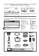
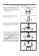
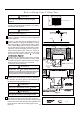

1. Check to see that you have received the following parts:
NOTE:
If you are uncertain of part description, refer to
exploded view illustration.
4
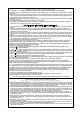
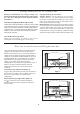
Unpacking Instructions
For your convenience, check-off boxes are provided next to each step. As each step is completed, place a check
mark in the box. This will insure that all steps have been completed and will be helpful in finding your place should
you be interrupted.
Do not install or use fan if any part is damaged or
missing. This product is designed to use only those
parts supplied with this product and/or any
accessories designated specifically for use with this
product by Fanimation. Substitution of parts or
accessories not designated for use with this product
by Fanimation could result in personal injury or
property damage.
otor sse ly
anger racket sse ly
ownrod anger all sse ly
Ceiling Canopy
Canopy crew Cover sse ly
otor Coupling Cover sse ly
lade Cover et
lade older et
lade et
ight late sse ly
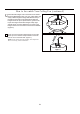
Light Kit Assembly
LED Assembly
teel Cap
ardware ags:
–
wenty eight
lade to lade holder
an ead errated crew
–
ineteen
lade holder to otor
an ead crew
–
our ire Connectors
Ceiling Canopy
Hanger Bracket
Assembly
Downrod/
Hanger Ball Assembly
Motor Coupling
Cover Assembly
Motor Assembly
Hardware Bag
Hand-Held
Remote
Steel Cap
Blade Holder Set
Blade
Set
Blade Cover Set
Canopy Screw
Cover Assembly
Light Plate Assembly
LED Assembly
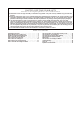
This manual is designed to make it as easy as possible for you to assemble,
install, operate and maintain your ceiling fan
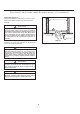
Tools Needed for Assembly
ne hillips head screwdriver
One stepladder
Four wire connectors
nstalled ire ength
ire i e
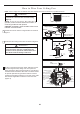
Before assembling your ceiling fan, refer to section
on proper method of wiring your fan (page 10). If you
feel you do not have enough wiring knowledge or
experience, have your fan installed by a licensed
electrician.
WARNING
!
One wire stripper
p to ft
ft
One lade
screwdriver
Materials
iring outlet o and o connectors ust e of type
re
uired y the local code he ini u wire would e a
conductor wire with ground of the following si e:
NOTE:
Place the parts from the loose parts bags in a small
container to keep them from being lost. If any parts are
missing contact your local retailer.
–
alance it
–
ag sse ly afety Ca le
Light Kit Assembly
– Two #8-32 Junction box screws,
stainless steel
– Two Flat Washer, stainless steel
Hand-Held Remote
Receiver Unit
Receiver
Unit