
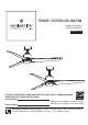
Installation Guide


CAUTION: INCORRECT WIRE CONNECTION COULD
DAMAGE THIS RECEIVER.
NOTE: If fan or supply wires are different colors than indicated, haYHWKLVXQLWLQVWDOOHGE\DTXDOL¿HGHOHFWULFLDQ
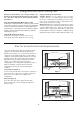
Figure 4
MAIN FUSE BOX
Figure 2
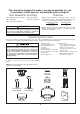
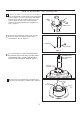
Figure 1
Figure 3
To avoid possible electrical shock, be sure electricity
gniriw erofeb xob esuf niam eht ta ffo denrut si
(Figure 2).
WARNING
NOTE:
If you are not sure if the outlet box is
grounded, contact a licensed electrician for advice, as
LWPXVWEHJURXQGHGIRUVDIHRSHUDWLRQ
x 8
WIRE
CONNECTORS
RECEIVER HARDWARE USED:
2. Slide the receiver into the hanger bracket as shown in
Figure 3.
WARNING
3. Connect wires using connectors as shown in Figure 4.
Check to see that all connections are tight, including
ground, and that no bare wire is visible at the wire
connectors. Do not operate fan until the blades are in
place. Noise and motor damage could result.
%/8(
%/$&.
:+,7(
%/$&.
:+,7(
/
1
$&32:(5
5('
*5$<
<(//2:
<(//2:
*5((1
LISTED
OUTLET
BOX
WHITE
BLACK
BLUE
BLACK & WHITE
GREEN-Ground Wire
From Hanger Bracket
GREEN-Ground Wire
From Hanger Ball
GREEN-Ground Wire
From Ceiling
YELLOW
GRAY
RED
GREEN / YELLOW
- Ground Wire (2)
From Receiver
*5281'
+$1*(5
%5$&.(7
+$1*(5
%$//
'&02725
%/$&.
$17(11$
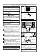
Figure 5
How to Wire Your Ceiling Fan
5HFHLYHU
5HFHLYHU
5HFHLYHU8QLW
+DQJHU%UDFNHW
NOTE: Supply wires
omitted for clarity
10
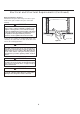
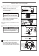
Dip Switch
ON
1 2 3 4 5
1. To set the code on receiver unit, slide dip switches to
the same positions as set on the remote. (Figure 1)
NOTE: The remote unit has 32 different code
FRPELQDWLRQV7RSUHYHQWSRVVLEOHLQWHUIHUHQFHIURPRUWR
other remote units, simply change the combination code
LQWKHUHPRWHDQGUHFHLYHU
NOTE: Factory setting is all up. Do not use this position.
4. After connections have been made, taking care not to
pinch the wires, put the white and green leads to one
side and the black leads towards the other side. The
wires should be spread apart with the grounded
conductor and the equipment-grounding conductor on
one side of the outlet box and the ungrounded conductor
on the other side. (Figure 5)