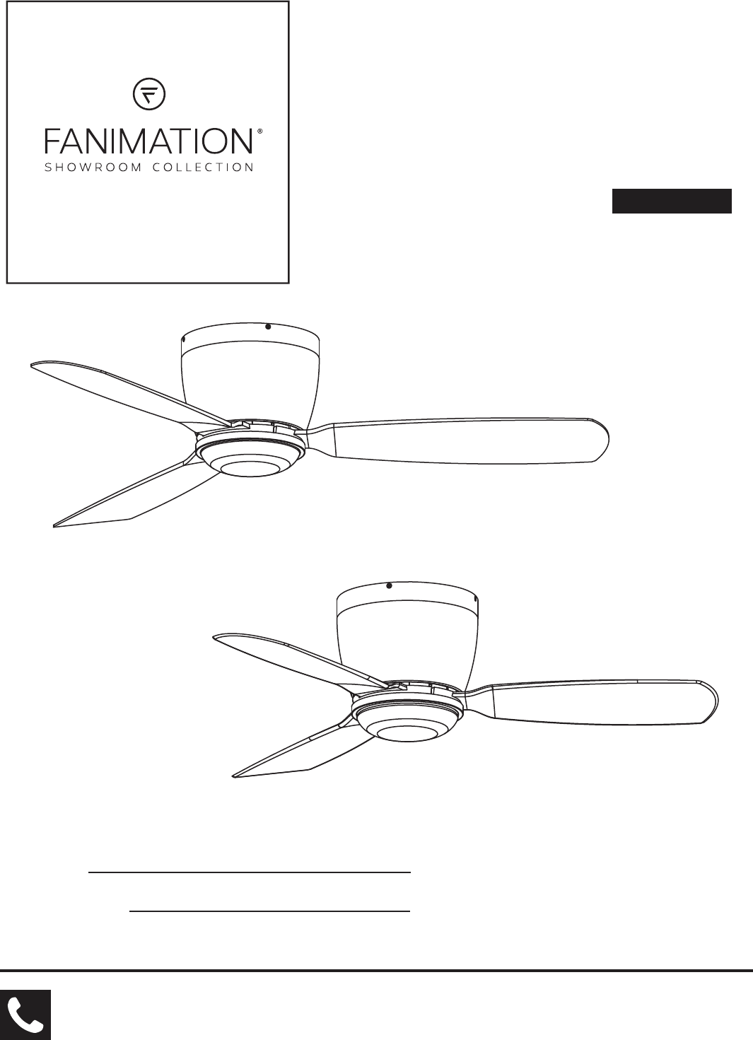
EMBRACE ™ CEILING FAN MODEL #FPS7955B** MODEL #FPS7981B** Español p. 19 ATTACH YOUR RECEIPT HERE AND REGISTER YOUR FAN AT FANIMATION.COM READ AND SAVE THESE INSTRUCTIONS Date Code Purchase Date FPS7955B** Net Weight 21.08 lbs (9.56 kgs) FPS7981B** Net Weight 18.61 lbs (8.44 kgs) For best and quick service please provide date code. You can find the date code on the Carton, Handheld Remote (inside of the battery compartment), Receiver or Ceiling Bracket.
Important Safety Instructions WARNING: To avoid fire, shock and serious personal injury, follow these instructions. 1. Read your owner’s manual and safety information before installing your new fan. Review the accompanying assembly diagrams. 2. Before servicing or cleaning unit, switch power off at service panel and lock service panel disconnecting means to prevent power from being switched on accidentally.
Table of Contents Unpacking Instructions. . . . . . . . . . . . . . . . . . . . . . . . . . . . . . . . . . . . . . . . . . . . . . . . . . . . . . . . . . . . . . . . . . . . . . . . . . . . . 4 . . . . . . . . . . . . . . . . . . . . . . . . . . . . . . . . . . . . . . . . . . . . . . . . . . . . . . . . . . . . . . . . . .5 Electrical and Structural Requirements . . . . . . . . . . . . . . . . . . . . . . . . . . . . . . . . . . . . . . . . . . . . . . . . . . . . . . . . . . . . . . .
This manual is designed to make it as easy as possible for you to assemble, install, operate, and maintain your ceiling fan Tools Needed for Assembly (Not Included) Materials Wiring outlet box and box connectors must be of type required by local code. The minimum wire would be a 3conductor (2-wire with ground) of the following size: WARNING Before assembling your ceiling fan, refer to section on proper method of wiring your fan (page 8).
Energy Efficient Use of Ceiling Fans Ceiling fan performance and energy savings rely heavily on the proper installation and use of the ceiling fan. Here are a few tips to ensure efficient product performance. Using the Ceiling Fan Year Round Summer Season: Use the ceiling fan in the counterclockwise direction. The airflow produced by the ceiling fan creates a wind-chill effect, making you “feel” cooler. Select a fan speed that provides a comfortable breeze, lower speeds consume less energy.
Electrical and Structural Requirements (Continued) Deep box with brace (Figure 3) Paired with a deep box, this hanger is meant to span between two joists and takes the place of wooden blocking. CEILING JOIST WARNING To reduce the risk of fire, electric shock, or personal injury, mount to outlet box marked acceptable for fan support of 15.9 kg (35 lbs) or less and use mounting screws provided with the outlet box.
How to Hang and Wire Your Ceiling Fan WARNING Ceiling The fan must be hung with at least 7´ of clearance from floor to blades. (Figure 1) WARNING To avoid possible electrical shock, be sure electricity is turned off at the main fuse box before hanging. NOTE: If you are not sure if the outlet box is grounded, contact a licensed electrician for advice, as it must be grounded for safe operation.
How to Hang and Wire Your Ceiling Fan (continued) 5. To set the code on receiver unit, slide dip switches to the same positions as set on the remote. (Figure 4) Receiver Unit NOTE: Factory setting is all up. Do not use this position. NOTE: The remote unit has 32 different code combinations. To prevent possible interference from or to other remote units, simply change the combination code in the remote and receiver. ON 1 DIP 2 3 4 5 Dip Switch Figure 4 6.
How to Assemble Your Ceiling Fan 1. Assemble the motor assembly to ceiling bracket assembly using the previously removed hex nuts and flat washers and securely tighten all hex nuts. (Figure1) Ceiling Bracket Assembly Motor Assembly Figure 1 2. Assemble the housing to ceiling bracket assembly using the previously removed screws and securely tighten all screws. (Figure 2) Ceiling Bracket Assembly Housing Figure 2 How to Assemble the Ceiling Fan Blades 1.
How to Assemble the Ceiling Fan Blades (continued) 2. Secure the blade holders to the bottom of the motor assembly using the 1/4 -20 screws. (Figure 2) NOTE: Periodically check blade holder hardware and Motor Assembly resecure if necessary. ! WARNING Blade Holder To reduce the risk of personal injury, do not bend the blade holders when installing, balancing the blades or cleaning the fan. Do not insert foreign objects in between the rotating blades.
How to Assemble the Light Kit or Cap (continued) 3. (Option A--for use with light kit) Securely attach 9-pin connector from motor assembly to wiring harness socket within light kit assembly. Assemble the light kit assembly to the light plate assembly using the previously removed screw in Step 2. (Figure 3) Motor Assembly Light Plate Assembly WARNING Light Kit Assembly The color labels on these two connectors must correspond to each other. Figure 3 4.
How to Operate Your Ceiling Fan 1. IMPORTANT: Using a full range dimmer switch (not included) to control fan speed will damage the fan. To reduce the risk of fire or electrical shock, do not use a full range dimmer switch to control the fan speed. (Figure 1) 2. Restore electrical power to the outlet box by turning the electricity on at the main fuse box.
How to Operate Your Ceiling Fan (continued) 6. If airflow is desired in the opposite direction, turn the fan off and wait for the blades to stop turning. Remove the glass or steel cap then slide the reverse switch of on the light kit assembly to the opposite position and turn fan on again. You might need to use the screwdriver or pin tool slide the reverse switch. Assemble the glsss or steel cap to the light plate assembly by twisting in a clockwise direction.
Troubleshooting WARNING For your own safety turn off power at fuse box or circuit breaker before trouble shooting your fan. Trouble 1. FAN WILL NOT START Probable Cause Suggested Remedy 1. Fuse or circuit breaker blown. 1. Check main and branch circuit fuses or circuit breakers. 2. Loose power line connections to the fan, or loose switch wire connections in the switch housing. 2. Check line wire connections to fan and switch wire connections in the switch housings.
Parts List 0RGHO )36 % )36 % Ref. # FPS7955B Part# Description 1 2 3 Housing 4 Blade Holder Set FPS7981B Part# AP796701** AP796701** AMA7955B** AMA7981B** P796703** P796703** AP796702** AP796702** %ODGH 6HW Ý )36 % 5 AP796744** %ODGH 6HW Ý )36 % AP796752** Light Plate Assembly 6 AP796705B** AP796705B** 7a. Switch Housing Assembly AP795503 AP798103 7b.
FPS7955B** Exploded-View Illustration 1 11 2 3 11 4 5 11 10 9 11 7a 6 7 7b 8 Figure 1 NOTE: 16
FPS7981B** Exploded-View Illustration 1 11 2 3 11 4 5 11 10 9 11 7a 6 7 7b 8 Figure 1 NOTE: 17
10983 Bennett Parkway Zionsville, IN 46077 Phone: 888-567-2055 Outside U.S.: 317-733-4113 FAX: 866-482-5215 FANIMATION.COM 2019/10 V.
VENTILADOR DE TECHO EMBRACE ™ MODELO #FPS7955B** MODELO #FPS7981B** ADJUNTE SU RECIBO AQUÍ Y REGISTRE SU VENTILADOR EN FANIMATION.COM LEA Y GUARDE ESTAS INSTRUCCIONES Código de fecha FPS7955B** Peso neto 9.56 kgs (21.08 lbs) Fecha de compra FPS7981B** Peso neto 8.44 kgs (18.61 lbs) Para ofrecer un servicio rápido y de calidad, por favor suministre el código de fecha.
Instrucciones de seguridad importantes ADVERTENCIA: Siga estas instrucciones para prevenir incendios, descargas eléctricas y lesiones personales graves. 1. Lea el manual del propietario y la información de seguridad antes de instalar su nuevo ventilador. Observe los diagramas de ensamblaje adjuntos. 2. Antes de llevar a cabo el mantenimiento o la limpieza de la unidad, desconecte la electricidad en el panel de servicio y bloquee los medios de desconexión del mismo para evitar que se active accidentalmente.
GARANTÍA LIMITADA DE POR VIDA Se extiende al comprador original del ventilador Fanimation solo desde un distribuidor/minorista autorizado de Fanimation 1.
Instrucciones para el desempaque A ADVERTENCIA AVERTISSEMENT No instale o utilice el ventilador si falta alguna pieza o si hay piezas dañadas. Este producto está diseñado para ser usado sólo con las piezas suministradas o los accesorios indicados por Fanimation específicamente para el mismo. La sustitución de piezas o accesorios no designados por Fanimation para usarse con este producto podría ocasionar lesiones personales o daños en el ventilador.
r v El nivel de rendimiento y ahorro de energía de los ventiladores de techo dependen de su correcta instalación yuso.Acontinuaciónlepresentamosalgunassugerencias para asegurar un rendimiento eficiente del producto. r cho Uso del ventilador de techo todo el año En verano: Use el ventilador de techo en sentido contrario a las agujas del reloj. El flujo de aire que produce el ventilador creará un efecto frío del aire que lo refrescará más.
Requisitos eléctricos y estructurales (cont.) Uso del soporte (Figura 3) Conectado a una caja de distribución eléctrica, este colgador sirve para abarcar el espacio entre dos vigas y ocupar el lugar de bloqueo de la madera. Vigas del techo ADVERTENCIA Para reducir el riesgo de incendios, descargas eléctricas o lesiones personales, fije el ventilador a la caja de distribución eléctrica marcada como aceptable para soporte de ventilador de 15,88kg (35lb).
Cómo colgar y realizar la instalación eléctrica del ventilador de techo ADVERTENCIA Techo Las aspas del ventilador deben estar suspendidas, al menos, a 2 m (7´) del piso (Figura 1) AVERTISSEMENT Le ventilateur doit être accroché de façon à ce que ses pales soient au moins à 7 pieds. (Figure 1) 2m (7 pies) como mínimo ADVERTENCIA Para evitar posibles descargas eléctricas, asegúrese de que la electricidad esté desconectada en la caja de fusibles principal antes de colgar el ventilador.
Cómo colgar y realizar la instalación eléctrica del ventilador de techo (cont.) NOTA: El mando a distancia incluido en este ventilador tiene 32 combinaciones diferentes de códigos. Para evitar posibles interferencias desde o hacia otros mandos a distancia, modifique el código de combinación de su transmisor y receptor. Unidad del receptor ON 5. Para configurar el código de unidad del receptor. Deslice los interruptores de código a las mismas posiciones que en el transmisor.
Cómo ensamblar el ventilador de techo 1. Instale la unidad del motor a la unidad de soporte de techo utilizando las tuercas hexagonales y arandelas planas anteriormente extraídas y fíjelas adecuadamente. (Figura 1) Unidad de soporte del ventilador Unidad de motor Figura 1 2. Instale la carcasa a la unidad de soporte de techo utilizando los tornillos anteriormente extraídos y fíjelos adecuadamente.
Cómo ensamblar su el kit de iluminación o la tapa PRECAUCIÓN A fin de reducir el riesgo descargas eléctricas, desconecte el circuito de suministro eléctrico al ventilador antes de instalar el kit de iluminación. Unidad del motor ATTENTION Pour réduire le risque d'électrocution, débranchez le circuit d'alimentation électrique du ventilateur avant d'installer le kit d'éclairage. Ensamble de la placa de iluminación 1.
Cómo ensamblar su el kit de iluminación o la tapa (cont.) 5. Para su uso con la tapa de acero Retire el conjunto de LED del conjunto de la ensamble del carcasa del interruptor quitando los tres tornillos y desenchufe el 2 conectores pin individuales. (Figura 5) Ensamble del carcasa del interruptor Unidad de LED Figura 5 6. Fije firmemente el conector de 9 pasadores de la unidad del motor al enchufe del mazo de cables dentro de la ensamble del carcasa del interruptor.
Cómo utilizar su control remoto de mano 1. El uso de un regulador de la intensidad completa (no incluido) para controlar la velocidad del ventilador dañará el dispositivo. Para reducir el riesgo de incendio o descarga eléctrica, no utilice dicho regulador para controlar la velocidad del ventilador. (Figura 1) 2. Restaure la fuente de alimentación de la toma de corriente enciendo la electricidad del fusible principal.
Cómo utilizar su control remoto de mano (cont.) 3. Para que el ventilador sea functional, instale las pila continuación, siga el proceso de fijación remota de código. Si no se utiliza el ventilador durante un largo periodo de tiempo, extraiga la batería para evitar cualquier daño alejado del calor o la humedad excesiva. (Figrua 3) ON 1 4. Para configurar el código del mando a distancia, Mueva los interruptores de código hasta colocar el código de selección en la posición arriba o abajo.
Cómo instalar su mando a distancia 1. Instalación de la placa de la pared: (Figura 1) Fije la placa de la pared usando los dos tornillos suministrados. Figura 1 Mantenimiento El único mantenimiento necesario para el ventilador de techo es una limpieza periódica. Al llevar a cabo la limpieza, use sólo un cepillo suave o un paño sin pelusas, para evitar rayar el acabado. No se requieren agentes abrasivos de limpieza; los mismos deben evitarse para prevenir daños en el acabado.
Solución de problemas ʆADVERTENCIA Para su propia seguridad, desconecte la electricidad de la caja de fusibles o disyuntor antes de solucionar problemas en su ventilador. ʆAVERTISSEMENT Pour votre sécurité, placez le coffret à fusibles ou le disjoncteur hors tension avant de tenter d’identifier tout problème pouvant affecter votre ventilateur. Problema 1. EL VENTILADOR NO ARRANCA Causa posible Solución sugerida 1. El fusible o el disyuntor están fundidos. 1.
Lista de piezas Modelos N.° FPS7955B** & FPS7981B** Ref. # FPS7955B** Pieza # N.° FPS7981B** Pieza # N.
Modelo N.
Modelo N.
10983 Bennett Parkway Zionsville, IN 46077 Llame sin cargo al (888) 567-2055 FAX (866) 482-5215 Desde fuera de los EE.UU., llame al (317) 733-4113 Visite nuestro sitio Web en www.fanimation.com 2019/10 V.