
Installation Guide

RC110 Remote Control
SPECIFICATION and INSTRUCTION SHEET
DESCRIPTION: One Ceiling Fan Only, 3 Speed Remote Control
ELECTRICAL SPECS: 1A, 120V, 60Hz Ceiling Fan
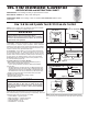
How to Wire and Operate Your RC110 Remote Control
NOTE: If fan or supply wires are different colors than indicated,
have this unit installed by a qualified electrician.
1. Setting the Code: The remote unit has 16 different code
combinations. It may be necessary to test a couple frequency
code settings to improve signal reception and/or eliminate
interference from other remote control household items. Multiple
fans should have different code settings to allow independent fan
control. To set the code, perform these steps.
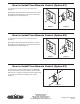
2. Transmitter: remove battery cover. Press firmly below arrow
and slide battery cover off. Slide code switches to your choice
of up or down position. Factory setting is all up. Do not use this
position. With a small screwdriver or ball point pen slide firmly up
or down (Figure 1a). Replace battery cover on the transmitter.
3. Receiver: Slide code switches to the same positions as set
on your transmitter (Figure 1b).
4. Installing Receiver in Hanger Bracket:
• Slide remote Receiver into the Hanger Bracket (Figure 2).
• Connect wires as indicated: (Figure 3)
– Green Hanger Bracket and Hanger Ball wires to BARE
(ground) wire.
– BLACK Receiver Unit wire (AC IN L) to BLACK supply wire.
–
WHITE Receiver Unit wire (AC IN N). to WHITE supply wire.
–
WHITE Receiver Unit wire (TO MOTOR N) to WHITE fan wire.
–
BLACK Receiver Unit wire (TO MOTOR L) to BLACK fan wire.
• Position all connected wires and receiver antenna to allow
installation of ceiling canopy.
• Reinstall ceiling canopy using canopy screws.
• Restore electrical power.
• HI Push Button – high fan speed
• MED Push Button – medium fan speed
• LOW Push Button – low fan speed
• OFF Push Button – fan off
• Center Button – no function
Figure 1bFigure 1a
Remote Transmitter
Unit Detail
Figure 2
Receiver Unit
Ceiling
Bracket
(Open End)
NOTE: Receiver wires omitted for clarity.
Figure 3
BLK-ANT
BL-AC IN L
WH-AC IN N
BLK-TO MOTOR L
WH-TO MOTOR N
GRN or BARE GROUND
GRN from hanger ball
GRN from bracket
120 VAC SUPPLY
(User Supplied)
▲
WARNING
Check to see that all connections are tight, including
ground, and that no bare wire is visible at the wire
connectors, except for the ground wire. Do not operate
fan until the blades is in place. Noise and fan damage
could result.
▲
WARNING
To avoid possible electrical shock, be sure electricity is
turned off at the main fuse box before wiring.
NOTE: If you are not sure if the outlet box is grounded,
contact a licensed electrician for advice, as it must be
grounded for safe operation.
Figure 4
3V, CR2032
BATTERY
2 PCS
Receiver Unit Detail
FAN MODEL USED: See Catalog or visit our website www.fanimation.com for more
information
5. Operating & Using Remote Transmitter (Figure 4):
Install two piece of 3 volt battery (If not using for long periods of
time, remove battery to prevent damage to transmitter). Store the
transmitter away from excess heat or humidity.
NOTE: Set fan switch to high speed before using
the remote control.
You can now use your speed control to select any of the 3-speeds plus
OFF.