
Installation and Operation Manual DBF 4XLT

4
Indicator Panel Installation
Step 1. Selecting Panel Location
The DBF4XLT indicator panel mounts near the dryer in a location that will be visible to the
operator of the dryer. The indicator panel is supplied with 50 feet of cable. Ensure that the
indicator panel and booster fan are located to allow their connection with this cable.
Step 2. Wiring and Mounting Panel
The indicator panel is a low voltage device that is not required to be installed in an electrical
junction box. If provided with clearance for the cable and terminal block it can be mounted to a
wall using appropriate fasteners.
If installer chooses to mount indicator panel in a single gang junction box (by others), it should
not be installed in a box that contains line voltage wiring or devices.
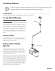
On the end of the 50 foot cable with stripped wires connect red wire to the positive (+) posi-
tion of the terminal block on the indicator panel. Connect black wire to the negative (-) position
of the terminal block on the indicator panel as shown in Figure 1.1.
Fan Installation
Step 1. Selecting Fan Location
The indicator panel is supplied with 50 feet of cable. Ensure that the indicator panel and boost
fan are located to allow their connection with this cable.
Fan must be mounted a minimum of 5 linear feet from the dryer outlet. In order to perform
recommended maintenance, fan location should allow sufficient access for service. Refer to
dimensional drawings shown on the next page.
NOTE: Steps 2 & 3 may be reversed.
Step 2. Mount Bracket
Using the 3/4" wood screws provided, attach the mounting bracket to a support beam at the
selected location. (See Figure 1.2) Fan mounting can be done at any angle, however, vertical
mounting is recommended to reduce condensation buildup in the fan. If a horizontal installation
is necessary and condensation buildup may pose a problem, a 1/4" hole drilled in the bottom
of the housing (along with an NPT insert (by others) and drain tubing) may be installed to allow
condensation to drain.
Step 3. Mount Fan
For proper operation, the control box (located on the fan) needs to be positioned properly. See
illustrations on Figure 1.3 show the correct control box position for fans that are mounted
horizontally, vertically and at an angle. The control box should also be positioned to provide
access to the indicator panel wiring and the tubing connections. Attach fan to the mounting
bracket with the self tapping 1/2" screws provided. Care should be taken not to strip the
housing. Although screw pilot holes are not required, 3/32" (or smaller) pilot holes are
recommended. See Figure 1.4
Step 4. Connect Indicator Panel Cable
Connect the end of the 50 foot cable that has a two position connector to the receptacle
located on the dryer booster fan control box.
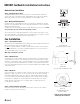
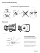
DBF4XLT Fan/Switch Installation Instructions
Mount Fan
(use 1/2" long self tapping screws)
Figure 1.3
Mounting Bracket and
Screw Locations
(using the wrong length screws
will damage the fan impeller)
Figure 1.4
Figure 1.1
Mount Bracket
(use 3/4" long wood screws)
Figure 1.2