Item #: 422974 Rev Date: 2017-05-01 Installation, Operation and Maintenance Manual ECHO™ 2800Xi Series Light Commercial Heat/Energy Recovery Ventilators Your ventilation system should be installed in conformance with the appropriate provincial/state requirements or, in the absence of such requirements, with the current edition of the National Building Code, and / or ASHRAE’s “Good Engineering Practices”. United States 10048 Industrial Blvd., Lenexa, KS, 66215 Tel.: 800.747.1762 • Fax: 800.487.
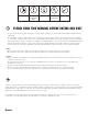
Note Warning/ Important note Information Technical information Practical tip PLEASE READ THIS MANUAL BEFORE INSTALLING UNIT • The key to proper and safe operating of the unit is to read this manual thoroughly, use the unit according to given guidelines and follow all safety requirements. • Before installation, careful consideration must be given to how this system will operate if connected to any other piece of mechanical equipment, i.e. an air handler, operating at a higher static pressure.
Table of content • Installation....................................................................................................................................................................................4 o Inspection...........................................................................................................................................................................4 o Location...............................................................................................
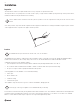
Installation Inspection The ECHO units are delivered on a pallet. Handles and necessary components are placed inside the unit. The inspection hatches are opened by the use of a 5/8” (16 mm) cap key, see figure below. To facilitate opening and closing of the inspection hatches, install the 2 handles that are placed inside the unit on delivery. The door handles must be locked before the unit is put into operation to ensure the required level of safety for the unit.
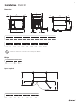
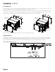
Installation (Cont'd) Dimensions I D G H G (c - c) D G B (c - c) (c - c) G H C B H F A A E B* C E D E K G F in mm in mm in mm in mm in mm in mm 73 7/16 1865 43 1/2 1105 51 1/16 1311 68 1/8 1730 4 102 2 7/8 73 G H I K (Drain 2x) Duct Dimensions in mm in mm in mm in mm in mm 2 11/16 68 50 3/8 1278 54 1/2 1384 3/4 NPT 19 NPT 14 x 34 352 x 859 * Dimensions B and D are centered to the mounting holes (Ø 3/4") Weight Models kg lbs HR
Installation (Cont'd) Port configuration The unit has hinged access doors on the front and removable panels on the back. The front left and right access doors are hinged for easy access to the filters, exchanger and fan motors while the back left and right panels are fastened to the unit. When facing the front access doors the outdoor and exhaust air duct connections are on the left side of the unit and the supply and return air duct connections are on the right side of the unit.
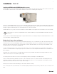
Installation (Cont'd) Installing the BYPASS module (BPM1434 module) accessory The BPM module accessory is an insulated recirculation damper box that is mounted on the side of the unit, over the outdoor air duct connection of the unit. It extends the outdoor air duct connection and has another duct connection for recirculating indoor tempered air. The purpose of the BPM1434 module accessory is to offer an alternative exchanger defrost method.
Installation (Cont'd) Weather hoods, louvers, ducts and dampers (Cont'd) Dampers are strongly recommended on both the supply & exhaust airstreams for proper unit operation and are often required to conform to regional requirements for ventilation systems. Dampers prevent unconditioned air infiltrating the space when the unit is stopped or during the exchanger defrost sequence.
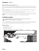
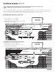
Installation examples (Cont'd) * Drawings are illustrations only and actual port locations and airflow directions may vary, consult unit spec sheets. * The BPM might need to be ducted depending on location of the installation. It is the responsibility of the installer to ensure all ductwork is sized and installed as designed to ensure the system will perform as intended. The amount of air (CFM) that an HRV/ERV will deliver is directly related to the total external static pressure (E.S.P.) of the system.
Installation examples (Cont'd) * Drawings are illustrations only and actual port locations and airflow directions may vary, consult unit spec sheets. * The BPM might need to be ducted depending on location of the installation. It is the responsibility of the installer to ensure all ductwork is sized and installed as designed to ensure the system will perform as intended. The amount of air (CFM) that an HRV/ERV will deliver is directly related to the total external static pressure (E.S.P.) of the system.
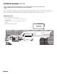
Unit components and electrical connections Electrical connection box All electrical connections are made in the electrical connection box found on the front of the unit. Remove the access panel by unscrewing the fasteners.
Unit components and electrical connections (Cont'd) Main power & circuit breaker connection The main power connection of this unit must be preceded by an all pole circuit breaker. The connection from this circuit breaker to the unit main power knockout must be run in flexible conduit (field supply & specify) for the reason that the unit electrical connection box is mounted on a hinged access panel used to service the fan motors.
Unit components and electrical connections (Cont'd) Pressure transducer modules As mentioned in the previous section, this unit is equipped with two (2) pressure transducer modules referred to as Pressure transducer exhaust (PTE) and Pressure transducer supply (PTS) (see unit wiring diagram). They are located inside of the unit on the return air side and can be accessed by opening the larger hinged access panel. Each module has two (2) pressure transducer.
Unit components and electrical connections (Cont'd) Installing the supply air temperature sensor A temperature sensor, as seen in the illustration below, is enclosed in the unit packaging on delivery. This temperature sensor is the supply air sensor and it must be mounted in the supply air duct no closer than 10 ft. (3 m) away from the unit. Using a two (2) wire conductor (field supplied and specified), connect the supply air sensor to terminal TB3 30-31 (see unit wiring diagram).
Unit components and electrical connections (Cont'd) Installing the unit external display The unit external display is delivered with a 32 ft. (10 m) cable that is used to connect the display to the Corrigo™ controller in the electrical connection box. See figure below for instruction on wiring the cable to the display. Find an appropriate place to install the display within 32 ft. (10 m) of the unit. Supplied cable comes with a connector to connect the display to the corrigo.
Unit operation System operation modes This unit has the following operation modes: • Starting up: The unit is performing the start sequence • Normal run: Normal speed or reduced speed ventilation active • Stop fan: The unit is performing the stop sequence • Stopped: Ventilation stopped • Recirculation: Exhaust air fan is stopped, Supply air fan is active and BPM module is open, room air is recirculated through the unit (Only available if unit is equipped with BPM module).
Unit operation (Cont'd) Controller display & start screen On startup, the start screen will be visible on the unit controller’s external display. The first line is the unit model name followed by the date and time (24h clock) and the current system operation mode. H2800Xi YYYY-MM-DD HH : MM SYSTEM: STOPPED The unit external display is used to configure & commission the unit. It is also used to troubleshoot and handle alarms generated by the controller.
Unit operation (Cont'd) Airflow control (CAV & airflow set points) By monitoring the pressure drop over the inlet ring of both fans, the unit control can calculate the airflow moved by each fan using a technique based on the Bernoulli and continuity equations. The unit control will modulate the analog output sent to each EC fan motor in order to maintain a given airflow set point. Follow the steps below to enter the airflow set points of the supply and exhaust air fans.
Unit operation (Cont'd) Time settings & schedule The unit controller has a year-based 24h clock function. This means that a weekly schedule with holiday periods for a full year can be set. The clock also has an automatic daylight saving time change-over. To set the date and time follow the steps below. 1 Time settings Temperature Go to Time settings by using the UP/DOWN arrow buttons.
Unit operation (Cont'd) Time settings & schedule (Cont'd) The schedules are set to inactive (00:00 – 00:00 Monday to Sunday & holidays) from the factory. If it is intended to have the unit operated by schedules then they have to be programmed in the field. Once the airflow set points, the time/date and the schedules have been programed, the unit will start up and operate at the given airflow set point when a schedule is active.
Unit operation (Cont'd) Exchanger defrost (Cont'd) 2 Exchanger frost prevention Exchanger deicing Go to Exchanger frost prevention by using the UP/DOWN arrow buttons. Select by pressing the RIGHT arrow button →Exchanger frost pre Cooling recovery Enthalpy control 3 Exchanger frost prevention Mode From this submenu, press the OK button to access the fields.
Unit operation (Cont'd) Recirculation (units equipped with the BPM module only) (Cont'd) 4 Configuring DI1 DI1 : From this submenu, press OK and change the DI from Not used to Recirculation. Press OK again to access the NO/NC field to set the digital input contact to either normally open (NO) OR normally closed (NC) based on what will be used to trigger the input. NO/NC: NO Signal: Recirculation Status: Off ↓ Once the input has been set, the recirculation mode can be configured.
Unit operation (Cont'd) Recirculation (units equipped with the BPM module only) (Cont'd) 2 Recirculation Actuator period time Locate Recirculation submenu by using the UP/DOWN arrow buttons and select it by pressing the RIGHT arrow button Step controllers →Recirculation Pretreatment 3 Recirculation Using the UP/DOWN arrow buttons, locate the use extra time group 5 in the Recirculation submenu then press the OK button and set the field value to Yes.
Unit operation (Cont'd) Extended running (Cont'd) A means of triggering the input will be required (field supplied and specified) and wired to terminals TB3 74 & 4, DI4 & +24VDC respectively (see wiring diagram). Remember to cut the power to the unit at the all pole circuit breaker before performing any electrical work. The Extended running digital input has precedence over the recirculation digital input and the normal, reduced and recirculation schedules.
Unit operation (Cont'd) Extended running (Cont'd) 2 Extended running Timer normal speed From the Time settings submenu locate Extended running and select it by pressing the RIGHT arrow button. Timer reduced speed →Extended running Holidays 3 Configure extended running From this submenu, press the OK button to access the fields and set values. Extended running 0 min Set the time value for extended running to remain active once the extended running input goes from on to off.
Unit operation (Cont'd) Fire alarm (cont'd) 2 Inputs/Outputs →Inputs/Outputs Locate Inputs/Outputs submenu by using the UP/DOWN arrow buttons and select it by pressing the RIGHT arrow button Sensor settings Control function Fan control 3 DI AI Go to DI by using the UP/DOWN arrow buttons. Select by pressing the RIGHT arrow button →DI UI AO 4 Configuring DI5 DI5 : From this submenu, use the UP/DOWN arrow buttons to locate DI5 and select it by pressing the RIGHT arrow button.
Unit operation (Cont'd) External switch (Cont'd) 3 DI AI Go to DI by using the UP/DOWN arrow buttons. Select by pressing the RIGHT arrow button →DI UI AO 4 Configuring DI6 From this submenu, use the UP/DOWN arrow buttons to locate DI6 and select it by pressing the RIGHT arrow button. Press OK again to access the NO/NC field to set the digital input contact to either normally open (NO) OR normally closed (NC) based on what will be used to trigger the input.
Alarm handling (Cont'd) Alarm # ≥Description Stop Auto reset Delay Supply air fan pressure control error 31 Alarm text: Supply air fan control error Cause: Supply air fan cannot maintain airflow setpoint No No 4 min Extract air fan pressure control error 32 Alarm text: Extract air fan control error Cause: Extract air fan cannot maintain airflow setpoint No No 4 min Manual supply air control 36 Alarm text: Manual supply air control Cause: manual control of supply temp No Yes 0s Ma
Alarm handling (Cont'd) 3 Acknowledged alarms If an alarm is acknowledged but the alarm conditions are still present, the alarm will remain in the log and the red LED will be on instead of flashing to indicate that the alarm is still active. Some alarms auto reset after the conditions are no longer met therefore they will clear from the log automatically.
Configuring BACnet MS/TP (port 1) (Cont'd) 5 Set MAC Address (default value = 10) Select MAC address by pressing the OK button until the cursor flashes on the first digit of the value below MAC. Use the UP/DOWN arrow Buttons to increase / decrease the selected digit value and the RIGHT/ LEFT arrow Buttons to move the cursor between digits. Once the required MAC address is displayed, press the OK button to store it in the unit controller.
Maintenance Make sure power to the unit is disconnected and locked out before attempting any maintenance work. The following components should also be inspected regularly and well maintained. The motor - The motors are factory balanced and lubricated for life. They require no maintenance. The unit - The inside of the unit should be wiped clean as needed. Condensation Pan - Units with drain hoses should have their line and connection checked regularly.
Limited Warranty • The Heat recovery aluminum core has a lifetime warranty. • The Energy recovery core has a 3 year warranty. • Fantech commercial HRV/ERV's have a warranty that is limited to 3 years on all parts from the date of purchase, including parts replaced during this time period. If there is no proof of purchase available, the date associated with the serial number will be used for the beginning of the warranty period.
Parts list 1 4 9 8 3 5 7 10 6 11 2 Description ECHO H2800Xi (95749) ECHO E2800Xi (95750) 1 R3G 355-PG60-25 414457 414457 2 Replacement core (3 cores per units) 414463 414493 3 Filter,Merv8,H2800Xi,Rep.Kit 422991 422991 4 Filter,Merv13,H2800Xi,Rep.Kit 422992 422992 5 TFMR,480/240/208/120v-24V,75VA 412749 412749 6 Controlunit E283 WEB Small 209664 209664 7 Auto.
Notes
Notes
Fantech reserves the right to make technical changes. For updated documentation please refer to www.fantech.