Installation and Maintenance Manual Manual de Instalación y Mantenimiento Item #: 405037 Rev Date: 2015-06-01 EPD Series Industrial Dehumidifier Déshumidificateur industriel Industrial Dehumidifier Deshumidificador industrialDeshumidificador industrial Read and Save These Instructions Lisez et conservez ces instructions Lea y guarde estas instrucciones EPD150LR • EPD180CR • EPD190LR • EPD250CR Operating Instructions Guide d'utilisation Instrucciones de uso United States 10048 Industrial Blvd.
Note Warning/ Important note Information Technical information Practical tip WARNINGS ADVERTENCIAS Plug into a grounded 3 prong outlet Conecte a un contacto de pared de conexión a tierra de 3 terminales. Do not remove ground prong. No quite la terminal de conexión a tierra. Do not use and adapter. Do not use an extension cord.
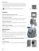
ircuit is required. The dehumidifier draws approx. 8 amps at 0°F, 60% RH. If used in a wet area, a ground fault interupter (GFI) is required. Hour Button (Fig. 4) For your safety and protection this appliance is manufactured Press HOURS button when thecord. dehuwith a the grounded plug on its power The power cord must 3 midifier cannot be plugged in and the be plugged into a properly groundedhour receptacle. If a groundmeter needs todoes be read.
Shut Down Mode Pressing the power button after the first minute of operation will initiate a shut-down mode. This mode Pump (Fig. 2) will last 15 minutes and will maintain the operation of the fan and purge pump to insurePurge all waterButton is In normal operation, the pump will automatremoved from the unit prior to moving or storing. Pressing the power button at any time during the shut ically empty the reservoir.
Venting / Ducting (Fig. 6) Twin rear outlets can accommodate two individual 5” ducts or one 10” lay flat duct to be attached. Disconnect power supply before cleaning This allows for warm dry air to be into different areas. Failure to follow these instructionsdirected can result in death, fire, or electrical Cleaning Fig. 8 5 shock Fig. 6 External Cleaning Use a non-flammable mild, non-abrasive soap and water solution. Wipe dry.
G COMPRESSOR CAPACITOR 60uF RED GREEN & YELLOW WHITE WHITE S R C COMPRESSOR WHITE O/L BROWN WHITE N WHITE BLACK BLACK J1 J2 PRESSURE SWITCH E5 J3 FLOAT E4 ELECTRONIC CONTROL BOARD E1 E3 E2 THERMISTOR BROWN BLUE fantech WHITE WHITE BLACK BROWN BLUE 2-78119-001 REV.
Electrical Requirements m m ti 7 Built in Electrical Safety Hour Button (Fig. 4) For your safety and protection this appliance is manufactured For 115V operation, a common grounded outlet on a 15 amp ircuit is required. The dehumidifier draws approx. 8 amps at 80°F, 60% RH. If used in a wet area, a ground fault interupter (GFI) is required. Deshumidificador industrial Press HOURS button when thecord.
Modo de apagado Si pulsa el botón de encendido luego del primer minuto de funcionamiento, iniciará el modo de apagado. Este Pump Purge Button (Fig. 2) modo durará 15 minutos y mantendrá el funcionamiento del ventilador y la bomba de purga para asegurar In normal operation, the pump will automatque se elimine toda el agua de la unidad antes de moverla o almacenarla. Si se pulsa el botón de encendido ically empty the reservoir.
Cambio de la batería Venting / Ducting (Fig. 6) Fig. 8 Twin rear outlets can accommodate two individual 5” ducts or one 10” lay flat duct to be attached. This allows for warm dry air to be antes de limpiar. directed into different areas. Desconecte la toma de corriente No seguir estas instrucciones podría provocar incendios, descargas eléctricas, e incluso la muerte. Fig. 6 Desconecte el deshumidificador de la toma de corriente.
Solución de problemas Servicio Un técnico de refrigeración calificado debe reparar todas las fugas de refrigerante. La unidad NO funciona: • ¿Se ha disparado el disyuntor? – Restablezca el disyuntor • Si la unidad se encuentra en un área húmeda, ¿está enchufada en un circuito protegido por un disyuntor diferencial? – La humedad excesiva disparará el disyuntor diferencial. Aléjela de esa área.
G COMPRESSOR CAPACITOR 60uF RED GREEN & YELLOW WHITE WHITE S R C COMPRESSOR WHITE O/L BROWN WHITE N WHITE BLACK J1 J2 PRESSURE SWITCH E5 J3 FLOAT E4 ELECTRONIC CONTROL BOARD E1 E3 E2 THERMISTOR BROWN BLUE BLACK WHITE WHITE BLACK BROWN BLUE 2-78119-001 REV.
WARRANTY One (1) Year Warranty This warranty supersedes all prior warranties WARRANTY - ONE YEAR This product is warranted against defects in material and workmanship for a period of one year from the date of purchase by the original purchaser. During this period, all parts and labor will be provided at no cost. Consumable parts (ie: light bulbs and filters) are not warranted or guaranteed for any length of time. This warranty is non transferable.
GARANTIA Garantia por un (1) Años Esta garantia de sin efecto cualquier otra garantia anterior GARANTÍA DE UN AÑO Se garantiza este producto contra defectos de fabricación y materiales por un periodo de un año a contar a partir de la fecha de compra del comprador original. Todas las partes y la mano de obra estarán cubiertas sin coste alguno durante este periodo.
NOTES fantech
NOTAS fantech
Fantech reserves the right to make technical changes. For updated documentation please refer to www.fantech.net Fantech se reserva el derecho de hacer modificaciones técnicas en cualquier momento. Para obtener la documentación actualizada, por favor consulte www.fantech.