
Install Instructions

Contactor for 3-Phase Fans, 208-230/460v
FADE Installation Manual 3
Wiring
SPECIAL WIRING PRECAUTIONS:
All installation should be wired according to the following diagrams. Failure to comply will cause the motor to "hum" or not work.
All units are pre-wired, just bring incoming supply into marked ports on terminal strip. (EXCEPT FOR 3 PHASE UNITS, please use a motor con-
tactor & TK leads to prevent damage to motor).
Models: FADE 8-4
115/230 Volt Single Phase Fans
Models: FADE 10-4, 12-4, 14-4, 16-4
120/230 Volt Single Phase Fans
Models: FADE 20-6
115 Volt Single Phase Fans
Models: FADE 18-4, 20-4, 22-6, 25-6
115/230 Volt Single Phase Fans
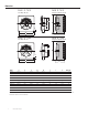
Wiring schematic for 4 lead motors, single phase
Notes:
1. All leads are color
coded as well as iden-
tified with an Alpha /
Alpha or Alpha /
Numeric code (i.e. TK
or Z2). This code may
be shown as a band
on the wire or on a
schematic on the
motor hub. Colors
should be verified against code band. If code band and color do not corre-
spond to schematics above, wire according to the code on the band.
2. Color of capacitor leads may be reversed. Fan operation will not be affected.
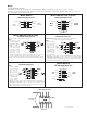
Models: FADE 20-4, 22-6, 25-6
460 Volt Three Phase Fans
Important note: For 460 volt operation, Orange (W2), Red (U2) and
Grey (V2) wires must be spliced together.
Notes:
1. Contactor should
be used. Control
coil should be
wired in series
with motor ther-
mal contacts (TK
leads) as shown
in diagram to pro-
vide thermal
motor protection.
2. All leads are color coded as well as identified with a band containing an
Alpha/Alpha or Alpha/Numeric code (i.e. TK or Z2). Colors should be verified
against code band. If code band and color do not correspond to schematics
above, wire according to the code on the band.
Models: FADE 20-4, 22-6, 25-6
230 Volt Three Phase Fans
Notes:
1. Contactor should
be used. Control
coil should be
wired in series
with motor ther-
mal contacts (TK
leads) as shown
in diagram to pro-
vide thermal
motor protection.
2. All leads are color coded as well as identified with a band containing an
Alpha/Alpha or Alpha/Numeric code (i.e. TK or Z2). Colors should be verified
against code band. If code band and color do not correspond to schematics
above, wire according to the code on the band.
Motor
Leads
White (TK)
Black (Z1)
Orange (Z2)
White (TK)
Brown (U1)
Capacitor
(Ground)
L (Black)
N (White)
Supply
Voltage
Blue (U2)
Green/Yellow
Motor
Leads
Brown
Black
Capacitor
(Ground)
L (Black)
N (White)
Supply
Voltage
Blue
Green/Yellow
Motor
Leads
Black
(Ground)
L (Black)
N (White)
Supply
Voltage
Blue
Green/Yellow
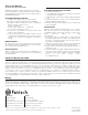
L1
Incoming
3-Phase Supply 208/230/460
Control Power
for Contactor
AC Contactor
L2 L3
TK TK L1 L2 L3 L3
Ground
T1 T2 T3
C1
C2
Motor Leads