
Install Instructions

4
fantech
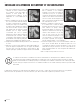
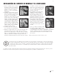
Multiple Location Switching Wiring Diagram
With Motor Speed Controller
Without Motor Speed Controller
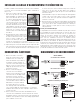
WARNING
Maximum torque that can be
applied to the terminal block
screws is 0.79 Nm (7 lb-in).
1. Remove the screws securing the terminal
box cover plate located on the side
of the fan. All fan motor connections
are pre-wired to an electrical terminal
strip. A 3/8" romex type cable restraint
connector will be needed to secure the
wiring through the knockout provided on
the side of the terminal box.
2. Bring incoming electrical service through
the romex connector and the fan
knockout. Be sure to place the connector
nut over the wiring coming into the
terminal box. There are two open ports
on the terminal strip. Using a small
regular screwdriver, tighten the neutral
(white) wire of the incoming supply under
the open terminal strip port labeled
"N". Tighten the line (black) wire of the
incoming supply under the open terminal
strip port labeled "L". Since the fan motor
is isolated within a plastic housing, grounding is not necessary.
3. Secure the romex connector. Secure the incoming supply with the
romex connector. Replace the fan terminal box cover. All fan motor
and capacitor connections have been pre-wired from the factory. No
additional fan wiring is necessary.
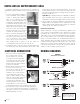
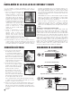
Liquid tight wiring – Top View
(For outside applications).
Romex wiring – Top View
ELECTRICAL CONNECTION WIRING DIAGRAMS
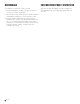
All Models
If a Vent/Light combination kit is purchased, the VLC vent/lights are
supplied with a separate installation instruction replacing steps 1 through
4.
1. Select the grill mounting point within the
area to be ventilated. To ease installation,
locations of framing beams within the
walls or joists supporting the ceiling
should be considered. Collar/damper is
provided with a perforated hanging strap
for attachment directly to a beam or joist.
Allow sufficient space between the collar/
damper and the beam to attach the duct
work. If the location of the grill does not
allow direct attachment, a cross-member
mounted to the framing should be used.
2. Place the mounting collar/damper in the
selected location and trace a circle onto
the surface. From the interior side of the
room, cut through the surface. Please
note: In order to assure a smoother finish
when mounting through a sheetrock or tile type ceiling, it is
recommended that a razor knife be used to make the cut.
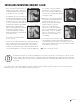
3. From within the attic or crawl space, place the mounting collar into the
hole until the edge of the collar is flush with the interior wall or ceiling
Side view grill and collar.
Mount Collar
INSTALLING DG SUPPLY/EXHAUST GRILL
surface. Attach collar to the support beam with the 2" wood screws
provided. Attach duct work. Secure using CB or FC clamps and/or duct
tape. When installing the damper into rigid type ducting, FC clamps or
duct tape should be used.
PLEASE NOTE: When attaching flex duct to the collar/damper combination
and an immediate elbow is necessary, be certain that the elbow is
installed with a "soft" bend to allow damper blades to operate properly.
4. Snap the grill into the mounting collar/damper. Grill should be pushed
tightly into place for an airtight fit. If there is a gap between the collar
and the ceiling it should be caulked to avoid air leakage. For subsequent
cleaning the grill can be pulled out and cleaned.
Flexible Duct Installation Hints
Flexible insulated duct is strongly recommended where allowed by local
code for bathroom exhaust applications, where ducting passes through
unconditioned space or where noise is a factor. Failure to use insulation
could result in excessive condensation buildup within the duct, and undesir-
able sound levels within the room. For the quietest possible installations,
Fantech recommends a minimum of 8' of insulated flexduct between any
exhaust grill and fan. When using flexible type duct work, duct should be
stretched as tight and straight as possible. Failure to do so could result in
dramatic loss of system performance. Flexible duct should be connected
to the fan with CB type clamps or duct tape. All connections should be as
airtight as possible to maximize system performance.