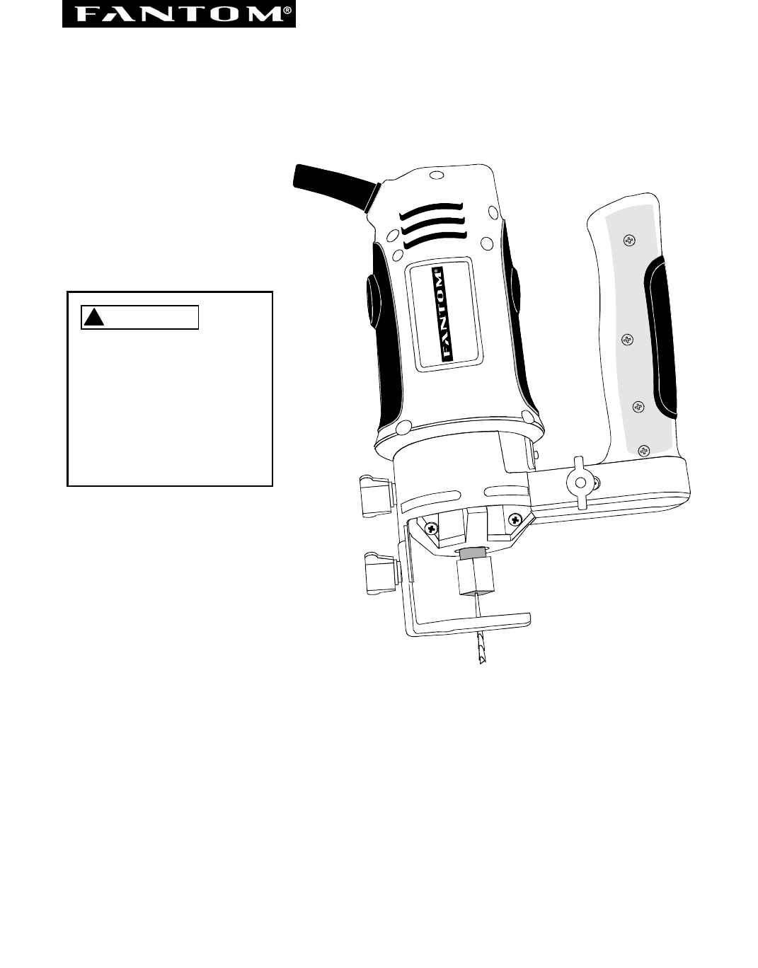
Owner’s Manual SPIN SAW / ROTARY TOOL KIT Model No. PT301H ! WARNING Always have one hand firmly placed on the tool body while operating. Never operate the tool by holding only the tool handle. CAUTION: Before using this Spin Saw/Rotary Tool, read this manual and follow all its Safety Rules and Operating Instructions. · · · · · Safety Instructions Accessories Assembly Operation Maintenance FANTOM, 178 West Service Road, Champlain, N.Y.
TABLE OF CONTENTS SECTION PAGE SECTION PAGE Product Specifications …………………. Power Tool Safety ..…………………….. Spin Saw/ Rotary Tool Safety .……... Electrical Requirements & Safety …….. 2 3 4 5 Carton Contents ………………………… Know Your Spin Saw ……………….. Assembly & Operation …….…………… Maintenance …………………………….. 6, 7 8 9 – 17 17 Warranty ….....................................…….
POWER TOOL SAFETY Dress properly. Do not wear loose clothing or jewelry. Contain long hair. Keep your hair, clothing and gloves away from moving parts. Loose clothing, jewelry or long hair can be caught in moving parts. GENERAL SAFETY RULES ! WARNING Read and understand all instructions. Failure to follow all instructions listed below may result in electric shock, fire and/or serious personal injury. Avoid accidental starting. Be sure switch is OFF before plugging in.
SPIN SAW SAFETY Always wear safety goggles and dust mask. Use only in well ventilated area. Using personal safety devices and working in a safe environment reduces risk of injury. SERVICE Tool service must be performed only by qualified personnel. Service or maintenance performed by unqualified personnel could result in risk of injury. ALWAYS WEAR EYE PROTECTION. Any power tool can throw foreign objects into your eyes which could cause permanent eye damage.
ELECTRICAL REQUIREMENTS & SAFETY DOUBLE INSULATION GUIDELINES FOR EXTENSION CORDS Make sure your extension cord is in good condition. When using an extension cord, be sure to use one heavy enough to carry the current the tool will draw. An undersized cord will cause a drop in line voltage resulting in loss of power and overheating. The table below shows the correct size to use according to cord length and nameplate ampere rating. If in doubt, use the next heavier gauge.
ACCESSORIES CARTON CONTENTS AVAILABLE ACCESSORIES ! UNPACKING AND CHECKING CARTON CONTENTS WARNING ! Use only accessories recommended for this spin saw. Follow instructions that accompany accessories. Use of improper accessories may cause injury to the operator or damage to the spin saw. ! WARNING If any part is missing or damaged, do not plug the spin saw into the power source until the missing or damaged part is replaced and assembly is complete. Carefully unpack the spin saw and all its parts.
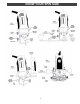
CARTON CONTENTS SPIN SAW COMPONENTS KEY A B C D E F G H I J K L M N O P Q R 7 DESCRIPTION Spin Saw Precision Handle with Sole Plate Freehand Sole Plate Attachment Circle Cutter Attachment Circle Cutter Installation Adapter Router Base Attachment 1/8” Collet 1/4” Collet 1/8” Lateral Style Drywall Cutter has "000028 HSS 1/8" marked on the shank of cutter 1/8” General Purpose Cutter has "000032" marked on the shank of cutter 1/8” Tile Bit Straight Router Bit Round Groove Router Bit Corner Round Router Bit C
KNOW YOUR SPIN SAW 8
ASSEMBLY & OPERATION ! WARNING INSTALLING CUTTING BITS – Cont’d Remove the plug from the power source before assembly, changing accessories or cutters and making adjustments. This safety action will help prevent accidental starting of the tool which could result in serious injury. 4. Insert new cutting bit (4) into the collet. ! WARNING Insert the bit all the way into the collet and then 1 1 pull it back between /16” and /8”.
ASSEMBLY & OPERATION CHANGING COLLET INSERT INSTALLING FREEHAND SOLE PLATE – cont’d The cutting bits for this tool are locked into place with a collet nut (1) and collet (see Fig. 3). The tool is 1 assembled at the factory with a /8” collet (2) which is used to hold the cutting bit. An additional ¼” collet (3) is supplied for holding SMALL router bits with a ¼” shank. 1. Remove accessory locking knob (1) from the base of the spin saw motor housing (see Fig. 4).
ASSEMBLY & OPERATION PRACTICE CUTS USING FREEHAND SOLE PLATE WARNING ! 6. Turn the switch ON. Have you read “POWER TOOL SAFETY”, “SPIN SAW SAFETY” and “ELECTRICAL SAFETY” on pages 3, 4 and 5 of this Manual? If not, please do it now before you operate this spin saw. Your safety depends on it! 7. When the motor is up to full speed, slowly tip the tool to an upright position, letting the bit cut into the workpiece (see Fig. 7).
ASSEMBLY & OPERATION CUTTING OUTLET OPENINGS IN DRYWALL – cont’d CUTTING OUTLET OPENINGS IN DRYWALL ! 6. Move the bit slowly to the right until you feel and hear the bit contacting the inside of the box. DANGER Do not attempt to use this tool to make cut-outs around any fixture or opening which has live electrical wires or on any wall which may have electrical wiring behind it.
ASSEMBLY & OPERATION ADJUSTING FREEHAND SOLE PLATE – Cont’d PRECISION HANDLE INSTALLING PRECISION HANDLE The precision handle is designed for use when precision control over the tool movement is desired. The comfortable handle can be used with either the right or left hand. Fig. 11 1. Remove accessory locking knob (1) from the base of the spin saw motor housing (see Fig. 10).
ASSEMBLY & OPERATION CIRCLE CUTTER CIRCLE CUTTER OPERATION – cont’d CIRCLE CUTTER OPERATION ! 5. Turn the switch ON. WARNING Unplug the tool from the power source before changing accessories, changing bits and making adjustments. 6. When the motor is up to full speed, slowly tip the tool and circle cutter assembly to an upright position, letting the bit cut into the workpiece (see Fig. 14). Be careful to keep the pivot point located at the center of the circle to be cut.
ASSEMBLY & OPERATION SETTING ROUTER DEPTH ROUTER BASE The router accessory converts your spin saw into a small hobby router that is capable of handling small ¼” shank router bits as well as the spiral cutting bit. The tilting base is ideal for bevel cutting. ! Depth of cutting is controlled by sliding the router base up and down in the adjusting sleeves. 1. Loosen both height adjusting knobs (1) by turning them counter clockwise (see Fig. 16). WARNING 2.
ASSEMBLY & OPERATION ROUTER BASE FREEHAND CUTTING AND ROUTING CUTTING STRAIGHT LINE WITH STRAIGHT EDGE When the router base accessory is installed on the spin saw, it will function as a small router to be used for freehand cutting of irregular shaped patterns. You can cut patterns out of the workpiece with the cutting bit or route patterns into the workpiece with small router bits. To cut a straight line, you can use a straight edge template to guide the router base. FREEHAND CUTTING 2.
OPERATION & MAINTENANCE MAINTENANCE ROUTER BASE EXTERNAL CLEANING CUTTING CURVED LINE WITH A TEMPLATE To cut a curved line, you can use a curved template to guide the router base. ! WARNING DO NOT use solvents when cleaning plastic parts. Most plastics are susceptible to damage from various types of commercial solvents and may be damaged by their use. Use clean cloth to remove dirt, dust, oil, grease, etc. 1. Make a template from hardboard or other similar material to the shape you require (see Fig.
Model PT301H TWO (2) YEAR LIMITED WARRANTY FANTOM warrants this product to be free from defects in material and workmanship for a period of two (2) years from the date of the original purchase, when utilized for normal household use, subject to the following conditions, exclusions and exceptions. If your appliance fails to operate properly while in use under normal household conditions within the warranty period, return the complete appliance and accessories, freight prepaid to FANTOM, 178 W. Service Rd.