GE Fanuc Automation Programmable Control Products TCP/IP Ethernet Communications for the Series 90™ PLC User's Manual GFK-1541B www.cadfamily.com EMail:cadserv21@hotmail.
GFL-002 Warnings, Cautions, and Notes as Used in this Publication Warning Warning notices are used in this publication to emphasize that hazardous voltages, currents, temperatures, or other conditions that could cause personal injury exist in this equipment or may be associated with its use. In situations where inattention could cause either personal injury or damage to equipment, a Warning notice is used. Caution Caution notices are used where equipment might be damaged if care is not taken.
Contents Chapter 1 Introduction .........................................................................................................1-1 The Ethernet Interface....................................................................................................... 1-2 Ethernet Interface Ports..................................................................................................... 1-4 The Station Manager Software .................................................................................
Contents Chapter 7 Troubleshooting...................................................................................................7-1 Diagnostic Tools Available for Troubleshooting.............................................................. 7-2 What to do if you Cannot Solve the Problem ................................................................... 7-3 PLC Fault Table................................................................................................................
Contents www.cadfamily.com EMail:cadserv21@hotmail.
Chapter Introduction 1 This manual describes the following Ethernet Interfaces for the Series 90 PLC: Series 90-30 PLC TCP/IP Ethernet Interface (IC693CMM321) Series 90-30 PLC CPU364 with embedded TCP/IP Ethernet Interface (IC693CPU364) Series 90-30 PLC CPU374 with embedded TCP/IP Ethernet Interface (IC693CPU374) Series 90-70 PLC TCP/IP Ethernet Interface (Type 2) (IC697CMM742) The general term, Ethernet Interface, will be used in this manual except when differences in the Interfaces requi
1 The Ethernet Interface The Ethernet Interface enables Series 90 PLCs to communicate with other Series 90 PLCs, with with GE Fanuc PLC programming software, and with applications developed using the SRTP protocol, such as CIMPLICITY® HMI. The Ethernet Interfaces described in this manual have “client/server” capability. As a “client” the Interfaces can initiate communications with other Series 90 PLCs containing Ethernet Interfaces. This is done from the PLC ladder program using the COMMREQ function.
1 Capabilities of the Ethernet Interface The Ethernet Interface brings to your PLC a great deal of capability. It will allow you to: Become operational quickly. The Ethernet Interface is made operational with very little effort. You need only install the Interface in the PLC rack or baseplate and use the PLC programming software to store basic configuration information to the module to make the basic SRTP server capability functional.
1 Ethernet Interface Ports The Ethernet Interfaces provide ports for connection to the Ethernet network as listed below.
1 Ethernet Media Various Ethernet baseband media (10Base...) can be interconnected by appropriate hubs or repeaters. Capabilities and limitations are defined in IEEE 802.3 Chapter 13, “System Considerations for Multi-Segment Networks”. This document is published by the Institute of Electrical and Electronics Engineers, Inc., 345 East 47th Street, New York, NY 10017-2394 USA. The Ethernet Interface can operate on any of the following media with the appropriate usersupplied transceiver cable and transceiver.
1 Special Considerations for Ethernet Interfaces with Embedded Switches Ethernet Interfaces that incorporate embedded switches (only the Series 90-30 CPU374) provide some additional connection options and have some additional installation and operation considerations. These Ethernet Interfaces provide two RJ-45 connectors on the front of the module.
1 The Station Manager Software The built-in Station Manager software provides on-line supervisory access to the Ethernet Interface, through either the Station Manager port or over the Ethernet cable. The Station Manager services on the Ethernet Interface include: An interactive set of commands for interrogating and controlling the station. Unrestricted access to observe internal statistics, an exception log, and configuration parameters.
1 www.cadfamily.com EMail:cadserv21@hotmail.
Chapter Installation 2 This chapter contains installation instructions for each Series 90 module that includes an Ethernet Interface.
2 Installing an IC693CMM321 Ethernet Interface Module The IC693CMM321Ethernet Interface mounts in a Series 90-30 PLC baseplate. It connects to an Ethernet network either directly through its 10Base-T port (10Base-T Type only), or through its AAUI port, which requires a user-provided transceiver and cable. If using the AAUI port, you may order a transceiver from GE Fanuc (see Appendix B for information) or supply your own equivalent transceiver. .
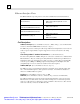
2 LEDs There are four LEDs on the CMM321 module. Each of these LEDs can be ON, OFF, or BLINKING. LED Indication Function OK State of the Ethernet Interface LAN Traffic on the network port FDX Configuration of Full Duplex mode. STAT An exception event has occurred All LEDs are briefly turned ON whenever a restart is performed in the Operational state by pressing and releasing the Restart pushbutton (described below). This allows you to verify that all LEDs are operational.
2 Restart and Enter Software Load State: Pressing and holding the Restart pushbutton until the bottom LED (STAT) turns ON (between 5 and 10 seconds) forces a restart and requests entrance to the Software Load state. A reload is used to install a software update into the module and is not part of normal operation. When the Restart pushbutton is pressed, all LEDs go out.
2 Ports on the CMM321 RS-232, RJ-11 Port (Station Manager Port) The RS-232, 6-pin, RJ-11 “phone jack” port is used to connect a terminal or terminal emulator to access the Station Manager software on the Ethernet Interface. A cable is needed to connect the terminal or emulator to the Ethernet Interface (see Appendix B, “Communications Ports Characteristics”). This port is also used to update the module’s firmware. Ethernet Ports The CMM321 has just one Ethernet interface.
2 Installing the CMM321 in the PLC For general information about module and system installation, refer to GFK-0356, Series 90-30 Programmable Controller Installation Manual. Equipment Required to Perform the Installation Procedures Make sure you have the items listed below before you begin. A Series 90-30 PLC CPU baseplate, or any Series 90-30 baseplate and a Series 90-30 CPU with power supply. The CMM321 requires CPU version 6.50 or higher for full functionality. CPU versions 5.03 to 6.
2 CMM321 Installation Use the following instructions as a guide when inserting a module into a slot in a baseplate. These instructions assume that the power supply on the baseplate is to your left. Warning Do not insert or remove modules with power applied. This could cause the PLC to Stop, damage the module, or result in personal injury. 1. Be sure the Series 90-30 PLC baseplate power is OFF. 2. Align the module with the desired base slot and connector.
2 CMM321 Configuration Before you can use the Ethernet Interface you must configure the module using the PLC programming software. The PLC programming software allows you to specify the modules and I/O that will reside in your Series 90-30 PLC rack(s). The Hand Held Programmer can not be used to configure the Ethernet Interface. For the Ethernet Interface specifically, the configuration software allows you to: Define the Status address of the Ethernet Interface.
2 Configuring the Interface Using the Logicmaster 90-30 Configuration Software To configure the CMM321, access the I/O Configuration rack screen in the Logicmaster 90-30 Configuration Package, and do the following: 1. Move the cursor to the desired rack and slot location. The slot may be either unconfigured or previously configured. 2. Press the Communications softkey, i.e., Comm (F6). 3. Press Ethernet (F2). 4. Press Enter to select the Ethernet Interface. 5. Configure the Ethernet parameters.
2 10.0.0.1 First PLC 10.0.0.2 Second PLC 10.0.0.3 Third PLC . . . . 10.0.0.255 PLC Programmer TCP or host Also, in this case, set the subnet mask, gateway IP address, and name server IP address to 0.0.0.0. Note If the isolated network is ever connected to another network, the IP addresses 10.0.0.1 through 10.0.0.255 must not be used and the subnet mask, gateway IP address, and name server IP address must be assigned by the network administrator.
2 Configuring Full-Duplex Operation Before setting the module to Full-Duplex operation, be certain that it is connected directly to a managed hub or switch that is manually configured for full-duplex operation on the port connected to the IC693CMM321. The default setting for the module is Half-Duplex. The Full Duplex parameter is an “advanced user parameter” that can only be changed by using the CHPARM (Change Parameter) command in the Station Manager softwar.
2 Verifying Proper Power-Up of the CMM321 Powering-up the Ethernet Interface After configuring the CMM321, follow the procedure below to be sure it is operating correctly. 1. Turn power OFF to the PLC for 3–5 seconds, then turn the power back ON. This will initiate a series of diagnostic tests. The OK LED will blink indicating the progress of power-up. 2. The LEDs will have the following pattern upon successful power-up. At this time the Ethernet Interface is fully operational and on-line.
2 States of the Series 90-30 CMM321 Ethernet Interface 1 Ethernet Interface Initializing 1 (approx.
2 LED Pattern ❍ ❍ ❍ ❍ OK (OFF) LAN (OFF) FDX (OFF) STAT (OFF) Where Stopped A Possible Cause Fatal Hardware Error. Hardware Failure ✫ ✫ ✫ ✫ OK (Slowblink) LAN (Slowblink) FDX (Slowblink) STAT (Slowblink) B Restart pushbutton until bottom LED turns ON. Station Manager LOAD command issued. Software corrupt. Did not configure slot using PLC Programmer. New CPU with no configuration. CPU not communicating with Ethernet Interface (Condition can last a maximum of 2 minutes.
2 Pinging TCP/IP Ethernet Interfaces on the Network PING (Packet InterNet Grouper) is the name of a program used on TCP/IP networks to test reachability of destinations by sending them an ICMP echo request message and waiting for a reply. Most nodes on TCP/IP networks, including the CMM321, implement a PING command. You should ping each installed Ethernet Interface. When the Ethernet Interface responds to the ping, it verifies that the interface is operational and configured properly.
2 Installing an IC693CPU364 with Embedded TCP/IP Ethernet Interface The CPU364 with Embedded Ethernet Interface is mounted on the Series 90-30 PLC baseplate. It is connected to an Ethernet network via a 10Base-T port or a user-provided transceiver cable and transceiver via an AAUI port.
2 LEDs There are four LEDs on the CPU364: EOK, LAN, STAT, and PS PORT (on some early models of the CPU364, the PS PORT LED is labeled “SNP”). The PS (Power Supply) PORT LED is not Ethernet related; it indicates the presence of serial traffic through the serial port of the PLC’s power supply. Each of the three Ethernet LEDs (EOK, LAN, and STAT) can be ON, OFF, BLINKING slow, or BLINKING fast.
2 Restart and Enter Software Load State: Pressing and holding the Restart pushbutton until the bottom LED (STAT) turns ON (between 5 and 10 seconds) forces a restart and requests entrance to the Software Load state. A reload is used to install a software update into the module and is not part of normal operation. When the Restart pushbutton is pressed, all LEDs go out.
2 Ports on the CPU364 RS-232, RJ-11 Port (Station Manager Port) The Station Manager port uses a 6-pin, RJ-11 “phone jack” connector. This port is used to connect a terminal or terminal emulator to access the Station Manager software on the Ethernet Interface. It is also used to connect to the PC Software Loader in case the communications software in the Ethernet Interface needs to be updated.
2 CPU364 Labels Default Station Address Label The Default Station Address label lists the MAC address to be used by this Interface. Serial Number Label The Serial Number Label indicates the serial number of this Interface. Replaceable Surface Mount Fuse A user-replaceable fuse is provided on the DC power that is supplied by the Ethernet Interface to the AAUI network port for use by an external transceiver. Replace only with a surface mount 2.69x2.69x6.
2 Installing the CPU364 in the PLC For general information about module and system installation, refer to GFK-0356, Series 90-30 Programmable Controller Installation Manual. Equipment Required to Perform the Installation Procedures Make sure you have the items listed below before you begin. A Series 90-30 PLC CPU baseplate with power supply. The Series 90-30 CPU364 requires PLC power supply IC693PWR321 (Revision K or later), IC693PWR322, or IC693PWR330.
2 CPU364 Configuration Before you can use the Ethernet Interface with the Series 90-30 PLC, you must configure the Interface using the PLC programming software. The PLC programming software allows you to specify the modules and I/O that will reside in your Series 90-30 PLC rack(s). The Hand Held Programmer can not be used to configure the Ethernet Interface. For the Ethernet Interface specifically, the configuration software allows you to: Define the Status address of the Ethernet Interface.
2 Configuring the Interface Using the Logicmaster 90-30 Configuration Software To configure the Ethernet Interface, access the I/O Configuration rack screen in the Logicmaster 90-30 Configuration Package, and do the following: 1. Move the cursor to the CPU slot (slot1) and press Zoom (F10) to access the CPU configuration screen. 2. If the current CPU is the CPU364, continue to step 3. Otherwise, press CPU (F1) to access the CPU selection menu.
2 Status Length: This is the sum of the LIS bits and the Channel Status bits. This value is automatically set to either 80 bits (for %I and %Q Status address locations) or 5 words (for %R, %AI, and %AQ Status address locations). IP Address, Subnet Mask, Gateway IP Address, and Name Server IP Address: These values should be assigned by the person in charge of your network (the network administrator). TCP/IP network administrators are familiar with these parameters.
2 Serial Port Parameters These parameters are for the RS-232, RJ-11 serial port on the CPU364 module. This port is used for both the Station Manager connection and for connecting to the Software Loader. The Software Loader settings take effect automatically when the Ethernet Interface enters the “Software Load” state. For all other states the Station Manager settings take effect. Refer to “Verifying Proper Power-Up of the Ethernet Interface”, for more information on states of the Ethernet Interface.
2 Verifying Proper Power-Up of the CPU364 Ethernet Interface After configuring the Ethernet Interface, follow the procedure below to verify that the Ethernet Interface is operating correctly. 1. Turn power OFF to the PLC for 3–5 seconds, then turn the power back ON. This will initiate a series of diagnostic tests. The EOK LED will blink indicating the progress of power-up. 2. The Ethernet LEDs will have the following pattern upon successful power-up.
2 States of the Series 90-30 CPU364 with Embedded TCP/IP Ethernet Interface 1 Ethernet Interface Initializing1 (approx.
2 LED Pattern ❍ EOK (OFF) ❍ LAN (OFF) ❍ STAT (OFF) Where Stopped A Possible Cause Fatal Hardware Error. Hardware Failure ✫ EOK (Slowblink) ✫ LAN (Slowblink) ✫ STAT (Slowblink) All LEDs blink in unison. ✫ EOK (Slowblink) ❍ LAN (OFF) ❍ STAT (OFF) B Software Loader C Waiting for Configuration from PLC ✫ EOK (Slowblink) D ●/✲/❍ LAN (ON/Traffic/OFF) ✫ STAT (Slowblink) Waiting for IP Address EOK and STAT blink in unison.
2 Pinging TCP/IP Ethernet Interfaces on the Network PING (Packet InterNet Grouper) is the name of a program used on TCP/IP networks to test reachability of destinations by sending them an ICMP echo request message and waiting for a reply. Most nodes on TCP/IP networks, including the Series 90-30 CPU364, implement a PING command. You should ping each installed Ethernet Interface. When the Ethernet Interface responds to the ping, it verifies that the interface is operational and configured properly.
2 Installing an IC693 CPU374 with Embedded TCP/IP Ethernet Interface The CPU374 with Embedded Ethernet Interface is mounted on the Series 90-30 PLC baseplate. It is connected to an Ethernet network via either or both of its auto-sensing 10Base-T/ 100Base TX ports.
2 The seven Ethernet LEDs are briefly turned ON whenever a restart is performed in the Operational state by pressing and releasing the Restart pushbutton (described below). This allows you to verify that the Ethernet LEDs are operational. Each RJ-45 port has two green LED indicators on it. The upper indicator, labeled LINK/ACT, lights when the link is physically present and blinks when traffic is detected on the port.
2 Installing the CPU374 in the PLC For general information about module and system installation, refer to GFK-0356, Series 90-30 Programmable Controller Installation Manual. Equipment Required to Perform the Installation Procedures Make sure you have the items listed below before you begin. A Series 90-30 PLC CPU baseplate with power supply. The Series 90-30 CPU374 requires PLC power supply IC693PWR321, (Revision K or later), IC693PWR322, or IC693PWR330.
2 CPU374 Configuration Before you can use the Ethernet Interface with the Series 90-30 PLC, you must configure the Interface using the PLC programming software. The PLC programming software allows you to specify the modules and I/O that will reside in your Series 90-30 PLC rack(s). The Hand Held Programmer can not be used to configure the Ethernet Interface. For the Ethernet Interface specifically, the configuration software allows you to: Define the Status address of the Ethernet Interface.
2 CPU374 Configuration Parameters Ethernet Parameters Configuration Mode: This is fixed as TCP/IP. Adapter Name: This field is set to 0.1 (the rack and slot of the Ethernet Interface) and cannot be changed. Status Address: The Status Reference Type is the location of the LAN Interface Status (LIS) bits (16 bits) and the Channel Status bits (64 bits). The Channel Status bits are always located immediately following the LAN Interface Status bits.
2 Also, in this case, set the subnet mask, and gateway IP address to 0.0.0.0. Note If the isolated network is ever connected to another network, the IP addresses 10.0.0.1 through 10.0.0.255 must not be used and the subnet mask,and gateway IP address must be assigned by the network administrator. The IP addresses must be assigned so that they are compatible with the connected network. Refer to Chapter 6, “Network Administration Support”, for more information on addressing.
2 Advanced User Parameters Advanced User Parameters may be set for the Ethernet Interface by creating an AUP file and putting it into the folder for the PLC application. The AUP file is a text file, created by any convenient text editor. The file name must be "AUP_0_1.APF". The first line of the file must consist only of the text: "AUP_0_1".
2 Verifying Proper Power-Up of the CPU374 Ethernet Interface After configuring the Interface, follow the procedure below to verify that the Ethernet Interface is operating correctly. 1. Turn power OFF to the PLC for 3–5 seconds, then turn the power back ON. This will initiate a series of diagnostic tests. The EOK LED will blink indicating the progress of power-up. 2. The Ethernet LEDs will have the following pattern upon successful power-up.
2 States of the Series 90-30 CPU374 with Embedded TCP/IP Ethernet Interface 1 Ethernet Interface 1 Initializing (approx.
2 LED Pattern ❍ EOK (OFF) ❍ LAN (OFF) ❍ STAT (OFF) ✫ EOK (Slowblink) ✫ LAN (Slowblink) ✫ STAT (Slowblink) All LEDs blink in unison. ✫ EOK (Slowblink) ❍ LAN (OFF) ❍ STAT (OFF) Where Stopped A Hardware Failure B Corrective Actions Make sure the PLC has power. Examine PLC Fault Table for clues. Recheck PLC Programmer configuration. Power off baseplate, inspect the Software corrupt. Interface for loose components, reseat the module, and Restart.
2 Pinging TCP/IP Ethernet Interfaces on the Network PING (Packet InterNet Grouper) is the name of a program used on TCP/IP networks to test reachability of destinations by sending them an ICMP echo request message and waiting for a reply. Most nodes on TCP/IP networks, including the Series 90-30 CPU374, implement a PING command. You should ping each installed Ethernet Interface. When the Ethernet Interface responds to the ping, it verifies that the interface is operational and configured properly.
2 Installing the IC697CMM742 Ethernet Interface The IC697CMM742 Ethernet Interface is mounted in a Series 90-70 PLC rack. It is connected to an Ethernet network via a 10Base-T port, a 10Base2 port, or a user-provided transceiver cable and transceiver via an AUI port.
2 All LEDs are briefly turned ON whenever a restart is performed in the Operational state by pressing and releasing the Restart pushbutton (described below). This allows you to verify that all LEDs are operational. See “Verifying Proper Power-Up of the Ethernet Interface” for more LED information. Ethernet Restart Pushbutton The Restart pushbutton serves four functions: LED test, Restart, Restart and enter Software Load state, and Restart and enter Maintenance state.
2 Restart and Enter Maintenance State: Pressing and holding the Restart pushbutton until the bottom two LEDs turn ON (approximately 10 seconds) forces a restart and requests entrance to the Maintenance state. Maintenance state must be invoked to change Advanced Parameters. While in Maintenance state, all Advanced Parameters revert to their default value. When the Restart pushbutton is pressed, all LEDs go out.
2 Ethernet Ports There are three Ethernet ports on the Ethernet Interface. Only one Ethernet port may be used at a time. The Ethernet Interface automatically detects the Ethernet port in use; special configuration is not required. (See also the topic “Disable Onboard 10Base2 Port Jumper” below.) Caution Do not connect or disconnect a transceiver or network cable to the AUI or BNC ports while power is applied to the PLC. This may blow the port fuse and/or cause permanent damage to the Ethernet Interface.
2 Installing the CMM742 in the PLC For general information about module and system installation, refer to GFK-0262, Series 90-70 Programmable Controller Installation Manual. Equipment Required to Perform the Installation Procedures Make sure you have the items listed below before you begin. Series 90-70 PLC rack. Series 90-70 power supply.
2 CMM742 Installation This section describes the physical mounting of the Ethernet Interface into the Series 90-70 PLC rack. For information on the installation procedures for the rack, Series 90-70 CPU, Power Supply, and other Series 90-70 modules, refer to GFK-0262, Series 90-70 Programmable Controller Installation Manual. Warning Do not insert or remove modules with power applied. This could cause the PLC to Stop, damage the module, or result in personal injury. 1.
2 CMM742 Configuration Before you can use the Ethernet Interface with the Series 90-70 PLC, you must configure the Interface using the PLC programming software. The PLC configuration software allows you to specify the modules and I/O that will reside in your Series 90-70 PLC rack(s). For the Ethernet Interface specifically, the configuration software allows you to: Define the Status address of the Ethernet Interface.
2 Configuring the Interface Using Logicmaster 90-70 Configuration Software To configure the Ethernet Interface, access the I/O Configuration rack screen in the Logicmaster 90-70 Configuration Package, and do the following: 1. Move the cursor to the desired rack and slot location. The slot may be either unconfigured or previously configured. 2. Press the Communications softkey, i.e., Comm (F6) 3. Press ethnet (F2). 4.
2 CMM742 Configuration Parameters Ethernet Parameters Configuration Mode: This is fixed as TCP/IP. Adapter Name: A symbolic name representation of the associated IP Address. The character set is listed in Chapter 6, “Network Administration Support”. The Adapter Name is associated with the IP address used in Ethernet Global Data. If supported in the PLC programming software, view all adapter names in Hardware Configuration by going to the Edit menu, choosing Rack Operations, and selecting Name Resolution.
2 Status Length: This is the sum of the LIS bits and the Channel Status bits. This value is automatically set to either 80 bits (for %I and %Q Status address locations) or 5 words (for %R, %AI, and %AQ Status address locations). Network Routing Pair #1, #2, #3: These parameters are used to define an IP routing partnership with another network adapter within the same PLC system.
2 Verifying Proper Power-Up of the CMM742 After configuring the Interface, follow the procedure below to verify that the Ethernet Interface is operating correctly. 1. Turn power OFF to the PLC for 3–5 seconds, then turn the power back ON. This will initiate a series of diagnostic tests. The MODULE OK LED will blink indicating the progress of power-up. 2. The LEDs will have the following pattern upon successful power-up. At this time the Ethernet Interface is fully operational and on-line.
2 States of the Series 90-70 CMM742 TCP/IP Ethernet Interface 1 The Ethernet Interface is initialized by - Powering-up the PLC - Storing a new configuration to the PLC with changes for the Ethernet Interface - Pressing the Restart pushbutton - Issuing a Station ManagerRESTART, LOAD, or MAINT command - Internal System Error occurring when Interface is Operational Ethernet Interface Initializing 1 (approx.
2 LED Pattern ❍ ❍ ❍ ❍ MODULE OK OFF) LAN ONLINE (OFF) SERIAL ACTIVE (OFF) STATUS (OFF) Where Stopped A Possible Cause Fatal Hardware Error. Hardware Failure ✫ ✫ ✫ ✫ MODULE OK (Slowblink) LAN ONLINE (Slowblink) SERIAL ACT. (Slowblink) STATUS (Slowblink) B Software Loader Restart pushbutton until the bottom LED turns ON. Station Manager LOAD command issued. Software corrupt. All LEDs blink in unison. ✫ ❍ ❍ ❍ MODULE OK (Slowblink) LAN ONLINE (OFF) SERIAL ACT.
2 Pinging TCP/IP Ethernet Interfaces on the Network PING (Packet InterNet Grouper) is the name of a program used on TCP/IP networks to test reachability of destinations by sending them an ICMP echo request message and waiting for a reply. Most nodes on TCP/IP networks, including the Series 90-70 Ethernet Interface (Type 2), implement a PING command. The user should ping each installed Ethernet Interface.
Chapter Programming SRTP Channel Commands 3 This chapter describes how to program PLC to PLC communications over the Ethernet network using SRTP Channel commands. To program Modbus/TCP Channel commands, see chapter 4.
3 The Communications Request This section describes the elements of the Communications Request. No programming of Communications Requests is required for PLCs acting as servers which are merely targets of other systems’ requests but do not themselves initiate requests.
3 COMMREQ Function Block The COMMREQ Function Block is the ladder instruction that triggers the execution of the Channel command. In the COMMREQ Function Block, you specify the rack and slot location of the Ethernet Interface, a task value, and the address of a location in memory that contains the Command Block. There is also a fault output on the COMMREQ Function Block that indicates certain programming errors.
3 Status Data There are several types of status data available to the client PLC logic program. LAN Interface Status Bits (LIS Bits): The LIS bits comprise bits 1–16 of the 80-bit status area. The location of this 80-bit status area is assigned using the Configuration software in the “Status Address” field. The LIS bits contain information on the status of the Local Area Network (LAN) and the Ethernet Interface itself.
3 Operation of the Communications Request The figure and text below explains how a Communications Request is executed. The figure specifically illustrates the successful operation of an Establish Read Channel command.
3 COMMREQ Function Block and Command Block This section describes the programming structures common to all Communications Requests: the COMMREQ Function Block and the Command Block. The COMMREQ Function Block The Communications Request is triggered when the logic program passes power to the COMMREQ Function Block.
3 TASK: For the Series 90-30 CPU364, this must always be set to 21 decimal (0015H). For the Series 90-30 Ethernet Interface and the Series 90-70 Ethernet Interface (Type2), this must always be set to zero. Caution Entering an incorrect TASK value may cause the Ethernet Interface to fail. OK Output: (Series 90-70 PLC only) The OK output is set if the PLC CPU has successfully delivered the COMMREQ to the Ethernet Interface.
3 COMMREQ Status Word: The Ethernet Interface updates the CRS word to show success or failure of the command. Command words 3 and 4 specify the PLC memory location of the CRS word. (Word 3) COMMREQ Status Word Memory Type: This word specifies the memory type for the CRS word. The memory types are listed in the table below: Type %R %AI %AQ %I %Q %T %M %G Value (Decimal) 8 10 12 16 70 18 72 20 74 22 76 56 86 Value (Hex.
3 Channel Commands There are five Channel commands: Establish Read Channel Establish Write Channel Send Information Report Abort Channel Retrieve Detailed Channel Status Establishing a Channel The Ethernet Interface transfers data to or from another PLC using a channel.
3 Establish Read Channel (2003) The Establish Read Channel command requests that a channel be associated with a remote PLC and that data from the remote PLC be transferred (periodically) to the local PLC. The Command Block specifies the period, the number of reads from the server (remote PLC) to perform, and the timeout allowed in waiting for each transfer to complete. The first read is performed immediately, regardless of the period specified.
3 (Word 7) Channel Command Number: Word 7 requests that a read channel be set up. If the command is processed successfully, it will result in attempting the specified number of transfers from the server to the client. (Word 8) Channel Number: Word 8 specifies the channel to be used for the read. This value must be in the range of 1–32 for the Series 90-70 Ethernet Interface (Type 2) and 1–16 for the Series 9030 Ethernet Interfaces.
3 (Word 12) Timeout for Each Read: Word 12 specifies the time (in hundredths of a second) the Ethernet Interface will wait for a read transfer to complete before setting the Channel Error bit and Detailed Channel Status words to indicate a non-fatal timeout error. The transfer can still complete even after a timeout occurs. As a result, an application can choose what to do if one occurs. If the timeout value is specified as zero, no timeout errors will be reported.
3 (Word 14) Local PLC - Memory Starting Address: Word 14 determines the starting address in the local PLC in which the data from the remote PLC is to be stored. The value entered is the offset (1based) from the beginning of PLC memory for the memory type and mode specified in Word 13. This offset will be either in bits, bytes, or words depending on the mode specified (for example, if Word 13=16 and Word 14=2, then the starting address will be %I9). Valid ranges of values depend on the PLC’s memory ranges.
3 (Words 20 – 23) Remote PLC - IP Address: Words 20–23 specify the four integers, one integer per word, of the dotted-decimal IP address of the remote PLC to be accessed. (Words 24–27) Remote PLC - Program Name: Words 24–27 specify the case-sensitive, zeroterminated and padded program name (also called task name, which can be found through the PROG Station Manager command on the server Ethernet Interface) to be used with access to remote %P or %L memory.
3 Example 2 Command Block–Example using a Network Address Name This example is the same as Example 1 except that the Network Address name of the Remote PLC (“PLC_1aa”) is used instead of its IP address. For more information on Network Address names, see the chapter: “Network Administration Support”. Establish a channel (Channel 5) to a remote PLC with a Network Address name of “PLC_1aa”. Return the COMMREQ Status word to %R10. Read remote PLC registers %R50–%R57 to local PLC registers %R100–%R107.
3 (Words 7 –17): See the descriptions in Example 1. (Word 18) Remote PLC - Network Address Type: Word 18 specifies the format of the remote PLC address. Currently, Word 18 must contain the value 1 or 3. A value of 1 indicates a dotteddecimal IP address expressed using a separate register for each decimal digit. A value of 3 indicates a Network Address name. See Example 1 for information on using address type 1.
3 Establish Write Channel (2004) The Establish Write Channel command requests that a channel be connected to a remote PLC and that data from the local PLC be transferred (periodically) to the remote PLC. The Command Block specifies the period, the number of writes to the server (remote PLC) to perform, and the timeout allowed in waiting for each transfer to complete. The first write is performed immediately, regardless of the period specified.
3 Status word. If the channel number is the same as a channel already in use, the channel will be re-tasked to perform this new command. (Word 9) Number of Write Repetitions: Word 9 specifies the number of writes to be performed before automatically completing the communications request and closing the channel. If this value is set to 1, only a single write will be issued. If this value is set to 0, writes will be issued on the requested period until the channel is aborted.
3 transferred is specified by the number of memory units of the data written to the remote PLC (Word 17). (Word 14) Local PLC - Memory Starting Address: Word 14 determines the starting address in the local PLC from which the data is to be written. The value entered is the offset (1-based) from the beginning of PLC memory for the memory type and mode specified in Word 13.
3 (Word 18) Remote PLC - Network Address Type: Word 18 specifies the format of the remote PLC address. Currently, Word 18 must contain the value 1 or 3. A value of 1 indicates a dotteddecimal IP address expressed using a separate register for each decimal digit. A value of 3 indicates a Network Address name. See Example 2 for information on using address type 3. (Word 19) Remote PLC - Network Address Length: Word 19 specifies the length in words of the remote PLC IP address.
3 Example 2 Command Block–Example using a Network Address name This example is the same as Example 1 except that the Network Address name of the Remote PLC (“PLC_1aa”) is used instead of its IP address. For more information on Network Address names, see the chapter: “Network Administration Support”. Establish a write channel (Channel 6) to a remote PLC with a Network Address name of “PLC_1aa”. Return the COMMREQ Status word to %R10. Write local PLC registers %R50– %R57 to remote PLC registers %R100–%R107.
3 (Words 7 –17): See the descriptions in Example 1. (Word 18) Remote PLC - Network Address Type: Word 18 specifies the format of the remote PLC address. Currently, Word 18 must contain the value 1 or 3. A value of 1 indicates a dotteddecimal IP address expressed using a separate register for each decimal digit. A value of 3 indicates a Network Address name. See Example 1 for information on using address type 1.
3 Send Information Report (2010) The Send Information Report COMMREQ requests that a particular block of memory within the PLC CPU reference tables be transferred periodically from an Ethernet Interface (SRTP Client) to a Host Application SRTP Server. The Command Block specifies the repetition period, the number of transfers to the server to perform, and the timeout allowed in waiting for each transfer to complete. The first send is performed immediately, regardless of the period specified.
3 If this value is set to 1, only a single transfer will be issued. If this value is set to 0, transfers will be issued on the requested period until the channel is aborted. (Word 10) Time Unit for Send Period: Words 10-11 together define how often the transfer is to be performed (transfer period). Word 10 specifies the time unit such as seconds or minutes for the send period. Word 11 specifies the number of those units. The choices for the time units are shown below.
3 (Word 14) Local PLC - Memory Starting Address: Word 14 determines the starting address in the local PLC from which the data is to be sent. The value entered is the offset (1-based) from the beginning of PLC memory for the memory type and mode specified in Word 13. This offset will be either in bits, bytes, or words depending on the mode specified (for example, if Word 13=16 and Word 14=2, then the starting address will be %I9). Valid ranges of values depend on the PLC’s memory ranges.
3 Example 2 Command Block–Example using a Network Address name This example is the same as Example 1 except that the Network Address name of the remote host (“PLC_1aa”) is used instead of its IP address. For more information on Network Address names, see the chapter: “Network Administration Support”. Establish a channel (Channel 7) to a remote host application server with a Network Address name of “PLC_1aa”. Return the COMMREQ Status word to %R10. Send local PLC registers %R50–%R57 to remote host.
3 (Words 7–17): See the descriptions in Example 1. (Word 18) Remote Host - Network Address Type: Word 18 specifies the format of the remote host’s address. Currently, Word 18 must contain the value 1 or 3. A value of 1 indicates a dotted-decimal IP address expressed using a separate register for each decimal digit. A value of 3 indicates a Network Address name. See Example 1 for information on using address type 1.
3 Abort Channel (2001) The Abort Channel command immediately disconnects an active channel from its remote PLC and renders the channel idle. The Channel Transfer bit, the Channel Error bit, and the Detailed Channel Status words for the channel are set to zero. Example Command Block Abort Channel 5. Return the COMMREQ Status word to %R10.
3 Retrieve Detailed Channel Status (2002) The Retrieve Detailed Channel Status command requests that the current Detailed Channel Status words be returned for a channel. The Detailed Channel Status words contain an active/inactive channel indicator and the last channel error codes seen. These two words of detailed status supplement the information available in the COMMREQ Status word and the Channel Status bits. The command has no effect on the value of the Channel Status bits.
3 (Word 8) Channel Number: The channel number in Word 8 specifies the channel whose status is to be read. This value must be a channel number in the range of 1–32 for Series 90-70 PLCs and 1–16 for Series 90-30 PLCs. (Word 9) Local PLC - Memory Type: Words 9 and 10 specify the starting point in the client CPU memory where the Detailed Channel Status words are to be written. The length of the transfer is implied and is equal to 2 words.
3 Status Data This section describes all the status data that is available to the ladder program to determine the state of the Ethernet Interface and its channels. Types of Status Data There are four main types of status data available to your ladder program: 1. OK Output of the COMMREQ Function Block.
3 The COMMREQ Status word (CRS word) is returned from the Ethernet Interface to the PLC CPU immediately if the Command Block contains a syntax error or if the command is local. For remote commands with no syntax error, it is returned either after the channel is established successfully and the first transfer has completed or if there is an error establishing the channel. The location of the CRS word is defined in the Command Block for the COMMREQ function.
3 LAN Interface Status (LIS) Bits The status bits normally occupy a single block of memory. The location of this block is specified during configuration of the Ethernet Interface. The first 16 bits of the block (see Table 5-3) are the LAN Interface Status (LIS) bits. The next 64 bits are the Channel Status bits (2 for each channel).
3 (Status Bit 7) RS-485 Port Fuse Blown (Series 90-30 Ethernet Interface and Series 90-70 Ethernet Interface (Type 2) only): This bit is set to 1 when the RS-485 Port fuse is blown. Otherwise it is set to 0. Operation is affected only if the Interface is in the Software Load state. This fuse is not field replaceable. (Status Bit 8) AAUI (90-30) or AUI/BNC (90-70) Fuse Blown: This bit is set to 1 when a network port fuse is blown. Otherwise, it is set to zero.
3 Each SRTP channel has a dedicated pair of bits as follows: (Status Bits 17, 19, 21 ... 79) Data Transfer Bit: This bit is normally set to 0. It is pulsed to 1 and back to 0 on successive PLC scans each time a transfer completes successfully. Do not assume that when the Data Transfer bit goes to 1 that a transfer has just completed during the last scan. The Data Transfer bit is not closely synchronized in time with the transfer.
3 Communications Status Words The COMMREQ Status word (CRS word) and the first word of the two Detailed Channel Status words (DCS words) report status and errors in the same format, as shown below. The second word of the DCS words indicates when the channel is active. The CRS word location is specified in Words 3 and 4 of the Command Block. The DCS words location is specified in the Retrieve Detailed Channel Status Command.
3 3. A status code of 1 in the low byte and 0 in the high byte indicates that the request was successful. All other non-zero values indicate errors. Refer to the tables below for a complete listing of major and minor error codes. The following tables list the error codes that are reported in the COMMREQ Status word after the execution of a COMMREQ function. These codes also may appear in Word 1 of the Detailed Channel Status words.
3 Minor Error Codes The meaning of each Minor Error Code depends upon the Major Error Code for which it is defined. Consult the appropriate Minor Error Code table for the indicated Major Error Code.
3 Minor Error Codes for Major Error Codes 5H and 85H (Continued) Error Status (Hexadecimal) F705H/F785H F805H/F885H F905H/F985H FC05H/FC85H FE05H/FE85H FF05H/FF85H Service Request Error Description Required to log in to a task for service. Invalid task name referenced. Task address out of range. I/O configuration is invalid. No privilege for attempted operation. Service request has been aborted.
3 Minor Error Codes for Major Error Code 11H (at Remote Server PLC) Continued 2E11H 2F11H 3011H 3111H 3211H 3311H 3411H 3511H 3611H 3711H 3811H 3911H 3A11H 3B11H 3C11H 3D11H 3E11H 3F11H 4011H 4111H 4211H 4311H 4411H E811H E911H EA11H EB11H EC11H FE11H The maximum number of transfers of this transfer type is already taking place. Cannot obtain a backplane transfer buffer. Cannot obtain resources other than backplane transfer buffers. Connection ID or block transfer ID is not valid.
3 Minor Error Codes for Major Error Code 11H (at Remote Server PLC) Continued 3111H 3211H 3311H 3411H 3611H 4811H 4911H 4C11H 4D11H 4E11H 4F11H Failure to register with backplane driver because the requested task is already registered. Unable to find resource necessary for backplane driver to process a service request. Bad sequence number detected in the service request because it is already in use. Invalid data detected that prevents backplane driver from completing a request.
3 Section 1: Section 2: Minor Error Codes for Major Error Code 90H (at Client PLC) - Continued 9690H 9790H 9890H 9A90H 9B90H 9C90H 9D90H 9E90H A190H A290H A490H B090H B190H B390H B590H Underlying TCP connection aborted (reset) by server end point. Underlying TCP connection aborted by client end point. The remote server has no Service Request Processor. Response to session request did not arrive in proper order. Session denied by server PLC. Data response did not arrive in proper order.
3 Controlling Communications in the Ladder Program This section provides tips on how to control communications in your ladder program. Only segments of actual ladder logic are included.
3 www.cadfamily.com EMail:cadserv21@hotmail.
3 Rung # 1: Input LANIFOK (bit 16 of the LAN Interface Status bits) monitors the health of the Ethernet Interface. If it is OK to send a COMMREQ, the LAN_OK coil is ON. LAN_OK is used as an interlock for Rungs 3–6. Rung # 2: Input BEGREAD triggers READREQ, which enables execution of the MOVE and COMMREQ functions. READREQ is a one-shot (Positive Transition) coil, activating once when BEGREAD transitions from OFF to ON.
3 FT Output is ON If after executing a COMMREQ Function, the FT Output is ON, then there is a programming error in one or more of the following areas. Invalid rack/slot specified. The module at this rack/slot is unable to receive a COMMREQ Command Block. Invalid Task ID. For the Series 90-30 Ethernet Interface and the Series 90-70 Ethernet Interface (Type 2), this value should always be zero. For the Series 90-30 CPU364, this value should always be 21 decimal (0015H).
3 Monitoring the Channel Error Bit This bit (normally 0) is the primary indicator for an error on a channel. It indicates any channel error, fatal or non-fatal. It does not necessarily indicate that the channel is down (idle). If this bit indicates an error: Initiate the Abort command and then reinitiate the Read or Write command, or if the error persists, Initiate the Retrieve Detailed Channel Status command to find out if the channel is down and possibly why it went down.
3 Managing Channels and TCP Connections In Certain Conditions TCP Connections Can Be Totally Consumed When you issue a COMMREQ to establish a read or write channel, a TCP connection is created, the transfer(s) are made, then upon completion of all the transfers, the TCP connection is terminated. It takes time to create and to terminate these connections.
Chapter Programming Modbus/TCP Channel Commands 4 This chapter describes how to program communications over the Ethernet network using Modbus/TCP® Channel commands. Details of the Communications Request (COMMREQ) function and the Modbus/TCP Channel commands are presented here. To program SRTP Channel commands, see chapter 3. To use the Modbus/TCP Server capability within the Ethernet Interfact, consult Appendix E about translating PLC reference memory addresses to Modbus Register addresses.
4 The Communications Request “Communications Request” is a term used to describe all the user elements required for correctly initiating Channel commands from a Series 90 PLC. This section describes the elements of the Communications Request. No programming of Communications Requests is required for PLCs acting as servers, which are merely targets of other systems’ requests, but do not themselves initiate requests.
4 COMMREQ Command Block The COMMREQ Command Block is a structure that contains information about the Channel command to be executed. The Command Block consists of two parts: Common Area - includes the address of the COMMREQ Status word (CRS word). Data Block Area - describes the Channel command to be executed. When the COMMREQ function is initiated, the Command Block is transferred to the Ethernet Interface for action.
4 Operation of the Communications Request The figure and text below explains how Communications Requests are executed to complete a data read from the remote Modbus/TCP device. The figure specifically illustrates the successful operation of a data read.
4 COMMREQ Function Block and Command Block This section describes the programming structures common to all Communications Requests: the COMMREQ Function Block and the Command Block. The COMMREQ Function Block The Communications Request is triggered when the logic program passes power to the COMMREQ Function Block.
4 TASK: For the Series 90-30 Ethernet Interface this must always be set to zero. Caution Entering an incorrect TASK value may cause the Ethernet Interface to fail. FT Output: The FT output is set if the PLC CPU (rather than the Ethernet Interface) detects that the COMMREQ fails. In this case, the other status indicators are not updated for this COMMREQ. The COMMREQ Command Block When the COMMREQ function is initiated, the Command Block is sent from the PLC CPU to the Ethernet Interface.
4 COMMREQ Status Word: The Ethernet Interface updates the CRS word to show success or failure of the command. Command words 3 and 4 specify the PLC memory location of the CRS word. (Word 3) COMMREQ Status Word Memory Type: This word specifies the memory type for the CRS word. The memory types are listed in the table below: Type %R %AI %AQ %I %Q %T %M %G Value (Decimal) 8 10 12 16 70 18 72 20 74 22 76 56 86 Value (Hex.
4 Modbus TCP Channel Commands This section describes the operation of the Channel commands. A detailed description and example of each Channel command is included. There are four Channel commands: Open a Modbus/TCP Connection Close a Modbus/TCP Connection ReadData from a Modbus/TCP Device to the PLC Write Data from the PLC to a Modbus/TCP Device Open a Modbus/TCP Client Connection (3000) The Modbus/TCP Ethernet Interface transfers data to or from another Modbus/TCP device using a channel.
4 Command 3000 Example Establish a channel (Channel 5) to a remote Modbus/TCP device at IP address 10.0.0.1. Return the COMMREQ Status word to %R10.
4 Close a Modbus/TCP Client Connection (3001) The application programcloses a Modbus/TCP Client Connection by issuing the Close Modbus/TCP Client Connection COMMREQ. The Close COMMREQ closes the underlying TCP connection and frees the channel for other communication tasks. An error response is returned if the channel number in the COMMREQ identifies a nonModbus/TCP Client connection or an inactive channel. Command 3001 Example Terminate the Modbus/TCP Client connection established on Channel 5.
4 Read Data from a Modbus/TCP Device (3003) The Read Data from a Modbus/TCP Device COMMREQ requests a data transfer from a Modbus/TCP device to the PLC. The Read Data COMMREQ must reference an active Modbus/TCP channel previously established with the Open Modbus/TCP Client Connection COMMREQ. Registers, Coils or Exception Status data may be read from the remote Modbus/TCP device. The Modbus Function Code specifies the data type.
4 Command 3003 Example 1 Read four Input Registers from Address 30200 in the remote Modbus/TCP device. Store the registers at location %R20. Return the COMMREQ Status word to %R10.
4 (Word 10) Local PLC Memory Type: Words 10-11 specify the location in the local PLC where the Ethernet Interface will store data received from the remote device Valid values for Word 10 are listed below.
4 Command 3003, Example 2 Read nine (9) Input Discretesfrom Address 10005 in the remote Modbus/TCP server. Store the registers at location %T3(bit mode). Return the COMMREQ Status word to %R10.
4 Command 3003, Example 3 – Read Exception Status Read the Exception Status from the remote Modbus/TCP server. Store the ExceptionData at location %Q4(bit mode). Return the COMMREQ Status word to %R10.
4 Write Data to a Modbus/TCP Device (3004) The Write Data to a Modbus/TCP Device COMMREQ requests a data transfer from the PLC to a Modbus/TCP server. The Write Data COMMREQ must reference an active Modbus/TCP channel previously established with the Open Modbus/TCP Client Connection COMMREQ. Registers or Coils may be written to the remote Modbus/TCP device. The Modbus Function Code specifies the data type.
4 Command 3004, Example 1 – Set Single Register Write one register from %AI10 to address 40200 in the remote Modbus/TCP server. Return the COMMREQ Status word to %R10. Use channel 6, a channel previously opened with the Open Modbus/TCP Client Connection COMMREQ.
4 Command 3004, Example 2 – Force Single Coil Set coil 10501 ON in the remote Modbus/TCP device using the value at %Q4. Return the COMMREQ Status word to %R10. Use channel 6, a channel previously opened with the Open Modbus/TCP Client Connection COMMREQ.
4 Command 3004, Example 3 – Set Multiple Registers Write the four registers from Discrete Input Memory (%I40 to) address 40200 in the remote Modbus/TCP server. Return the COMMREQ Status word to %R10. Use channel 6, a channel previously opened with the Open Modbus/TCP Client Connection COMMREQ.
4 Status Data This section describes all the status data that is available to the ladder program to determine the state of the Ethernet Interface and its Modbus/TCP channels. Types of Status Data There are three main types of status data available to your ladder program: 1. FT Output of the COMMREQ Function Block.
4 Description of the Status Data The errors and status reported in each type of status data are described below. FT Output of the COMMREQ Function Block The FT Output passes power upon the following errors: Invalid rack/slot specified. The module at this rack/slot is unable to receive a COMMREQ. Invalid Task ID. Invalid Data Block length (zero or greater than 128). Too many simultaneous active COMMREQs (overloading either the PLC CPU or the Ethernet Interface).
4 (Status Bit 8) AAUI (90-30) Fuse Blown: This bit is set to 1 when a network port fuse is blown. Otherwise, it is set to zero. This failure is also reported to the PLC Fault Table as “LAN interface hardware failure; switched off network”. Operation on other ports is not affected. This problem can be caused by a defective transceiver, shorted network or transceiver cable, or a defective Ethernet Interface. The fuse is not fieldreplacable so the module must be returned to GE Fanuc for repair.
4 Communications Status Words The COMMREQ Status word (CRS word) reports status in the format shown below. The CRS word location is specified in Words 3 and 4 of the Command Block. CRS Word in Hex Format High Low 00 00 Minor Error Codes (high byte) Success and Major Error Codes (low byte) There are several points to remember when interpreting the contents of the COMMREQ Status word: 1. Display the Status Words in hexadecimal form to more easily differentiate the high and low bytes.
4 Minor Error Codes The meaning of each Minor Error Code depends upon the Major Error Code for which it is defined. Consult the appropriate Minor Error Code table for the indicated Major Error Code. Minor Error Codes for Major Error Codes 90H (Client API Error) Error Status Service Request Error Description (Hexadecimal) 8190H COMMREQ data block too short for the command. 8390H Invalid server memory type. 8690H Zero server unit length is not allowed. 8790H Device unit length is too large.
4 Minor Error Codes for Major Error Code 91H (Remote Server Device Error Codes) Error Status (Hexadecimal) Error Description 0191H Illegal Function. The function code received in the query is not an allowable action for the server. This may be because the function code is only applicable to newer controllers, and was not implemented in the unit selected.
4 Controlling Communications in the Ladder Program This section provides tips on how to control communications in your ladder program. Only segments of actual ladder logic are included.
4 COMMREQ Example The input values for the Block Move Functions in this example are taken from the Open Modbus/TCP Connection (3000), Modbus/TCP Read (3003), and Close Modbus/TCP Connection (3001) Examples in this chapter. Nicknames are used in this example to make the ladder program easier to follow. LANIFOK is bit 16 of the LAN Interface Status bits. LAN_OK is bit 13 of the LAN Interface Status bits. All other nicknames can be assigned as you choose.
4 Rung # 4: The BLKMV INT functions set up the COMMREQ Command Block contents. When this rung is activated, the constant operands are moved into the memory beginning at the address indicated in the instruction. The constant operands in this example are defined in the Open Modbus/TCP Connection Example in this chapter. 5 6 Rung # 5: The COMMREQ Function Block has three input parameters and one output parameter.
4 7 8 9 Rung # 7: When OPEN_SUCCESS is set it triggers READ_REQ, which enables execution of the BLKMOV, MOVE and COMMREQ functions for the Modbus/TCP Read Commreq. READ_REQ is a one-shot (Positive Transition) coil, activating once when OPEN_SUCCESS transitions from OFF to ON. Rung # 8: The MOVE WORD function moves a zero to the CRS word referenced in the Command Block (see rung #9). This clears the CRS word. This rung also resets the READ_FLT output coil of the COMMREQ Function Block in rung #10.
4 10 11 12 13 Rung # 10: The COMMREQ Function Block has three input parameters and one output parameter. The IN field points to the starting location of the Command Block parameters (%R00301 in this example). The SYSID field of the COMMREQ Function Block defines the target rack and slot of the Ethernet Interface to receive the command data. This is a hexadecimal word value that gives the rack (high byte) and slot (low byte) location of the Ethernet Interface module.
4 Commreq. CLOSE_REQ is a one-shot (Positive Transition) coil, activating once when READ_SUCCESS transitions from OFF to ON. Rung # 13: The MOVE WORD function moves a zero to the CRS word referenced in the Command Block (see rung #9). This clears the CRS word. This rung also resets the CLOSE_FLT output coil of the COMMREQ Function Block in rung #15. 14 15 16 Rung # 14: The BLKMV INT functions set up the COMMREQ Command Block contents.
4 The IN field points to the starting location of the Command Block parameters (%R00301 in this example). The SYSID field of the COMMREQ Function Block defines the target rack and slot of the Ethernet Interface to receive the command data. This is a hexadecimal word value that gives the rack (high byte) and slot (low byte) location of the Ethernet Interface module.
4 Troubleshooting a Ladder Program As mentioned, there are several forms of status data which can be used in your ladder program. The use of the LAN Interface OK bit in the LAN Interface Status Word was described in the ladder program fragment above. Some of the status data can be used to troubleshoot your program in its developmental stage. The two primary sources of this data are the FT Output on the COMMREQ Function Block and the COMMREQ Status word (CRS word).
4 Monitoring the Communications Channel Once you have a working ladder program, you can use the status data to monitor your communications activity and take the desired action upon certain events. Monitoring the COMMREQ Status Word It is critical to monitor the CRS word for each COMMREQ function you initiate. First, zero the associated CRS word before executing the COMMREQ function. Then when the CRS word becomes non-zero, you know the Ethernet Interface has updated it.
Chapter Ethernet Global Data 5 This chapter discusses how to plan and configure an Ethernet Global Data (EGD) system. GFK-1541B Overview of EGD Configuring EGD Adapter Names, Aliases, and Groups Exchange Status Word Simple Network Time Protocol (SNTP) www.cadfamily.com EMail:cadserv21@hotmail.
5 Overview of EGD This section describes Ethernet Global Data in general terms. It also provides key information you need to plan and configure your Ethernet Global Data system. Ethernet Global Data allows one device (the producer) to share a portion of its internal memory (the exchange) with one or more other devices (the consumers) at a regularly scheduled periodic rate. This exchange is uniquely distinguished by a set of identifiers, the Producer ID and Exchange ID.
5 Producer The producer is the device that will periodically produce new samples of data from its local internal memory. The producer is uniquely identified by the Producer ID. The Producer ID is a dotted-decimal number (for example, 0.0.0.1). Although this number is in IP address form, it is not used as an IP address; it is used simply to uniquely identify a particular PLC on the network.
5 Asynchronous Operation of EGD The production and consumption of EGD is asynchronous. The period timers for the producer and consumer are independent of each other. In addition, the initiation of the production and consumption of EGD can occur at different times. The figure below illustrates the asynchronous aspect of EGD in all Ethernet Interfaces except the Series 90-30 CPU374. In the Series 90-30 CPU374, there is no consumer period.
5 Effect of PLC Modes and Actions on EGD Operations The table below indicates what happens to the configuration and operation of EGD when in different PLC modes and when certain PLC actions take place. For example, the normal PLC mode for EGD operation is RUN with Outputs enabled. In this PLC mode, EGD remains configured and exchanges are both produced and consumed. If the PLC mode is set to STOP with I/O disabled, the Producer ID remains configured, but production and consumption stop.
5 Configuration Planning Producer and Consumer Periods for PLCs Follow these guidelines for the producer and consumer periods. Set the producer period and the consumer period to the same value. This makes the system easier to troubleshoot and makes network resource usage more efficient. Do not produce and consume data faster than is required by your application. This reduces the load on the network and on the devices, providing capacity for other transfers.
5 Allowable Data Types in Exchanges Boolean type variables are not allowed; neither are Boolean-Array variables. If discrete point references such as %I or %Q are used to define a variable, you must define them as Byte-Array, Word-Array, or Dword-Array variables. This implies that a variable consisting of discrete point references must be defined in blocks of 8 points if it is defined as a Byte-Array, 16 points if Word-Array, and 32 points if DWord-Array. Discrete memory must be byte-aligned.
5 General PLC Timing Considerations when using EGD When designing applications using EGD, it is important to understand that the Ethernet Interface and PLC CPU share internal memory for EGD operations. This shared memory interface is represented by the diagram below.
5 Naming Conventions If you follow consistent naming conventions for your Ethernet Global Data system, it will be much easier to configure EGD. These naming conventions include the following items: Equipment Folder Name – This is the name of the program folder that you assign when creating a hardware configuration and program for a PLC. It can represent the name of a PLC. Producer ID – This identifies the EGD producer and is configured in the Ethernet Global Data dialog box.
5 Before You Configure EGD Exchanges Before you begin configuring EGD exchanges you will need to collect a considerable amount of information about the PLCs in your system. It is a good idea to record this data so that when you are ready to configure the exchanges in the PLC programming software, all pertinent information will be easily found. The tables that follow represent one way of recording this information. Use these tables or design your own method for recording the information outlined below.
5 Recording Exchange Information The produced/consumed exchanges tables below were designed with columns that match up with the fields in the Ethernet Global Data dialog box. These tables contain a definition of ALL the exchanges in the entire EGD system. The Local Producer ID column indicates in which PLC a given exchange is to be configured.
5 Configuring EGD This section describes how to configure EGD using the Ethernet Global Data rack operation in the Windows-based PLC programming software (if supported). The main topics covered are: Exchange Definitions Configuring Ethernet Global Data (with examples) Exchange Definitions The produced and consumed data exchange definitions that follow describe the fields to be filled in via the Ethernet Global Data rack operation in the PLC programming software.
5 Producer Period A value with the possible range of 10–3,600,000 (10 milliseconds to 1 hour) representing the scheduled repetition period at which the data is to be produced on the network. In the PLC, the Ethernet Interface will produce the data at this interval independent of when the CPU updates the data sample. The default is 200 milliseconds. For the CPU374, the range is 2 milliseconds to 1 hour. The CPU374 also allows a zero producer period which indicates producing “as fast as possible”.
5 Consumed Data Exchange Definition The information to be received by the consumer and the exchange details are defined in the Consumed Exchanges tab of the Ethernet Global Data dialog box. The consumed data exchange definition contains the following information: Field Details Local Producer ID A value in the form of a dotted-decimal IP address that uniquely identifies the Ethernet Global Data device across the network.
5 Status Word Time Stamp Exchange Variables A variable that identifies the memory location where the status value for the consumed exchange will be placed. Valid memory types are listed later in this chapter. A variable that identifies the memory location where the timestamp of the last data packet will be placed. The timestamp is not an actual date, it is an 8-byte value representing the time elapsed since midnight, January 1, 1970.
5 Configuring Ethernet Global Data Once you have collected all the essential information for your EGD system, connect to each PLC and configure the exchanges. For each PLC: 1. With the PLC programming software, open the Equipment folder for the PLC. 2. Open Hardware Configuration. 3. Choose Module Configuration and assign an adapter name to each Ethernet Interface in the PLC that will be producing or consuming Ethernet Global Data.
5 Example 1: EGD Configuration Using IP Addresses to Identify Consumers There are two PLCs in this simple EGD system. PLC1 is the producer and PLC2 is the consumer of a single Ethernet Global Data exchange. The consumer in this example is identified by IP address. Network-synchronized time stamping is not used. The identification of the PLCs and the details of the exchange are shown in the tables below.
5 Example 2: EGD Configuration Using a Group ID to Identify Consumers There are three PLCs in this EGD system using the Group ID feature. PLC1 is the producer and PLC2 and PLC3 are the consumers of a single Ethernet Global Data exchange. The consumers in this example are identified by Group ID. Network-synchronized time stamping is not used. The identification of the PLCs and the details of the exchange are shown in the tables below.
5 Example 3: EGD Configuration Using a Symbolic Name to Identify Consumers There are three PLCs in this more complex EGD system using three Ethernet Global Data exchanges. PLC1 contains two Ethernet Interfaces (designated A and B), one of which is both a producer and a consumer. PLC2 is a consumer only. And PLC3 is both a producer and a consumer. The Adapter Names are used as the symbolic names to identify the consumer PLCs. No aliases have been configured, so DDP name resolution will be used.
5 Consumed Exchanges Information – EXAMPLE 3 Local Exchange Producer ID ID 0.0.0.1 0.0.0.2 0.0.0.3 Local Adapter Name 2 3 1 PLC1_A PLC2 PLC3 Remote Group Consumer Update Producer ID ID Period Timeout 0.0.0.3 0.0.0.1 0.0.0.1 0 0 0 1000 1000 1000 2000 2000 2000 Status Word Time Stamp Stat2 Stat3 Stat1 n/a n/a n/a Variable List for Consumed Exchanges – EXAMPLE 3 Local Remote Exchange Producer ID Producer ID ID 0.0.0.1 0.0.0.1 0.0.0.2 0.0.0.3 0.0.0.3 0.0.0.3 0.0.0.1 0.0.0.
5 Adapter Names, Aliases, and Groups Setting Adapter Names and Aliases in the Windows-Based Programming Software This section does not apply to the Series 90-30 CPU374, because it uses the rack and slot as its adapter name and does not support aliases for remote network adapters. Configuring the Ethernet Interface Adapter Name If an Ethernet Interface will be used in Ethernet Global Data exchanges, you must specify an adapter name for the Interface.
5 Group Usage The group concept in Ethernet Global Data exchanges allows many EGD devices to simultaneously consume the same data produced by one producing EGD device. This capability is valuable for efficient bandwidth utilization in systems where data may be shared among multiple devices. This capability is made available by a technique called Multicasting. For more information on Multicasting, see the topic “Multicast IP Addresses” in the chapter: “Network Administration Support”.
5 Exchange Status Word The Exchange Status word allows an Ethernet Global Data user to obtain the operating status of a given exchange definition. The PLC will write status codes into the Exchange Status word. The Exchange Status word is changed upon exchange configuration* and when a producer/consumer period expires, and the value will be set for the entire period.
5 Exchange Status Word Error Codes The following table shows the error codes that can be written to the Exchange Status word. Value (Dec.) Produced / Consumed 0 P/C 1 P 1 C 3 C Error No new status event has occurred. No error currently exists. No error, data consumed. SNTP error. . Specification error. 4 P/C 6 C 7 C 10 P/C 12 P/C 16 P 18 P/C 22 P/C 26 P/C 28 P/C Refresh timeout without data. Data after refresh timeout. IP Layer not currently initialized.
5 Simple Network Time Protocol (SNTP) SNTP is a method of synchronizing the internal clocks in a network's Ethernet Interfaces to an external source. In an SNTP system, a computer on the network (called an SNTP server), sends out a periodic timing message to all of the SNTP-capable Ethernet Interfaces on the network, which keep their internal clocks synchronized with this common SNTP timing message.
5 Multiple SNTP Servers To guard against loss of SNTP timing messages, multiple SNTP time servers can be tracked on a network. An Ethernet Interface can maintain timing information from up to four total SNTP time servers at a time. Each server assigns a stratum number that determines its priority. The message from the server with the lowest stratum number is used by the Ethernet Interface until communication with that server is lost.
Chapter Network Administration Support 6 This chapter discusses information related to how host computers are identified on the network and how data is routed to a host computer. The main topics covered are: GFK-1541B • IP Addressing • Gateways • Subnets and Multiple Gateways • Configuring Multiple Gateways • Network Address Naming Architecture • MAC Addressing www.cadfamily.com EMail:cadserv21@hotmail.
6 IP Addressing Each TCP/IP node on a network must have a unique IP address. The TCP/IP Ethernet Interface is such a node, as is a PC running TCP/IP. There may be other nodes on the network that are not involved with communications to the PLCs, but no matter what their function, each TCP/IP node must have its own IP address. It is the IP address that identifies each node on the IP network (or system of connected networks). The term “host” is often used to identify a node on a network.
6 IP Addresses Reserved for Private Networks RFC 1918 reserves IP addresses in the following ranges to be used for private networks. 10.0.0.0 – 10.255.255.255 (Class A) 172.16.0.0 – 172.31.255.255 (Class B) 192.168.0.0 – 192.168.255.255 (Class C) Multicast IP Addresses Multicast IP Addresses are used in multicasting, a technique that allows delivery of a single packet of data to multiple nodes on the network.
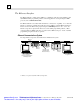
6 Gateways Gateways (also known as routers) connect individual physical networks into a system of networks. When a node needs to communicate with a node on another physical network, a gateway transfers the data between the two networks. Networks Connected by a Gateway The following example shows Gateway G connecting Network 1 with Network 2. a45405 A 172.16.0.1 Network 1 172.16.0.2 G Gateway B 172.17.0.1 C 172.17.0.3 172.17.0.2 Network 2 When host B with IP address 172.17.0.
6 Subnets and Multiple Gateways For a site requiring a large network (such as a Class A network) the number of entries in the routing tables of a site’s internal gateways could number in the millions if no internal network structure is superimposed on the address definition. The solution to this problem is subnetting. Subnets allow a site’s network administrators to divide a large network into several smaller networks while still presenting the overall network as one single entity to the outside world.
6 Example: Network Divided into Two Subnets The new network configuration dividing Network 2 into Subnets 2.1 and 2.2 is shown below. A 172.16.0.1 Network 1 172.16.0.2 G1 Gateway B C 172.17.64.1 172.17.64.3 172.17.64.2 (Sub)Network 2.1 172.17.64.4 G2 Gateway D E 172.17.128.3 172.17.128.1 172.17.128.2 (Sub)Network 2.2 Here, a second network with Hosts D and E has been added. Gateway G2 connects Subnet 2.1 with Subnet 2.2.
6 Configuring Multiple Gateways Multiple Gateways are supported on the Series 90-70 Ethernet Interface (Type 2) and the Series 90-30 CPU364 and CPU374 only. An Ethernet Interface with the Multiple Gateways feature has the ability to route packets not only through a single default gateway, but also through additional gateways located on the local subnet. The gateway that is configured in the Ethernet Interface’s hardware configuration (using the PLC programming software) is defined as the default gateway.
6 However, if you configure a routing table for PLCs B and C, their data may be forwarded to other gateways. If Gateway G1 has been configured as the default gateway, the routing table could have an entry for Subnet 2.2 via Gateway G2 and Subnet 2.3 via Gateway G3. If the data is not destined for either remote Subnet 2.2 or Subnet 2.3, then the data would be routed to Gateway G1, the default gateway. To configure a PLC on Subnet 2.1 to be able to communicate with Network 1, Subnet 2.2, and Subnet 2.
6 Network Address Naming Architecture Naming architecture provides users the ability to refer to their Ethernet Interfaces in terms of a symbolic name rather than a numerical address. This name, commonly referred to as the network address name, can be constructed from the following character set: a-z A-Z 0-9 ` ~ ! @ # $ % ^ & * ( ) _ + | - = \ { } [ ] : ” ; ’ < > ? . / Note The comma is not a supported character for network address names.
6 Local Name Table Name Assignment The second aspect involves building a name table that contains a mapping of symbolic names to associated IP addresses. A name assigned in this table is also known as an alias. A network address name assigned in the local name table can be resolved by Local Name Table Name Resolution, as described in a following section.
6 DDP Name Resolution If local name table name resolution fails, DDP (a GE Fanuc naming protocol) is used to dynamically resolve the symbolic name. DDP name resolution involves the client node broadcasting a message on the network asking if any node recognizes the symbolic name. If a node does recognize the name, it responds and supplies the associated IP address. The client can then proceed with communication directly to that IP address. DDP uses broadcast traffic to perform name resolution.
6 MAC Addresses Note It is highly recommended that you use the unique default MAC supplied within the Ethernet Interface. However, you may override that default with a MAC address of your own choosing with the Station Manager CHPARM MACADDR command (See GFK-1186, TCP/IP Ethernet Communications for the Series 90 PLC Station Manager Manual.) The MAC address is a 48-bit binary number that identifies the station on the physical network. The MAC address is typically expressed as a 12-digit hexadecimal number.
Chapter Troubleshooting 7 This chapter is a guide to troubleshooting and problem isolation for the Series 90-30 Ethernet Interface, the Series 90-30 CPU364, the Series 90-30 CPU374, and the Series 90-70 Ethernet Interface (Type 2). GFK-1541B Diagnostic Tools Available for Troubleshooting What to do if you Cannot Solve the Problem PLC Fault Table www.cadfamily.com EMail:cadserv21@hotmail.
7 Diagnostic Tools Available for Troubleshooting There are several tools to assist you in diagnosing problems with the Series 90 Ethernet Interface and the network. Use the Ethernet Interface LEDs to troubleshoot a problem on power-up of the Ethernet Interface and for an immediate visual summary of the operational state of the Interface. Use the Series 90 PLC Fault Table to troubleshoot a problem once the Interface is running.
7 What to do if you Cannot Solve the Problem If, after using the troubleshooting guide, you still cannot solve your problem, call GE Fanuc Automation - NA. Please have the following information available when you call. The Name and Catalog Number marked on the product. Description of symptoms of problem. Depending on the problem, you may also be asked for the following information: The ladder logic application program and the PLC sweep time at the time the problem occurred.
7 PLC Fault Table The PLC Fault Table can be accessed in PLC programming software. If you are experiencing a problem with the Ethernet Interface, check the PLC Fault Table for a fault message, then refer to the table that follows in this chapter for instructions on what to do about the problem. To access the details of a PLC Fault Table entry: For Windows-based PLC programming software, double-click the Fault Table entry and the details are displayed as “fault extra data”.
7 PLC Fault Table Descriptions PLC Fault User Action Backplane communications with PLC fault; lost request User Action: Check to make sure you are not sending COMMREQs faster than the Ethernet Interface can process them. If problem persists, contact GE Fanuc Automation - NA. Bad local application request; discarded request User Action: Check for valid COMMREQ command code. If problem persists, contact GE Fanuc Automation NA.
7 PLC Fault Table Descriptions (Continued) PLC Fault LAN I/F can’t init - check parms; running soft Sw utl User Action Internal system error. User Action: If problem persists, contact GE Fanuc Automation - NA. LAN I/F capacity exceeded; discarded request Verify that connection limits are not being exceeded. LAN interface hardware failure; switched off network User Action: Replace Ethernet Interface.
Appendix Glossary A This appendix contains a list of conventional communications terms. Adapter Name A name assigned to locally identify a module (e.g., an Ethernet Interface) in the local station. (See also Network Address Name.) Address Administration The assignment of LAN addresses locally or on a universal basis. Address Field The part of a Protocol Data Unit (PDU) that contains an address.
A Carrier Sense In a Local Area Network, an ongoing activity of a network node to detect whether another node is transmitting. Carrier Sense Multiple Access with Collision Detection (CSMA/CD) A bus network in which the medium access control protocol requires carrier sense and in which exception conditions caused by collisions are resolved by retransmission. Channel An association in a client PLC between the PLC application program and an Ethernet Interface in that same PLC.
A CSMA/CD See Carrier Sense Multiple Access with Collision Detection. Data Communications Equipment (DCE) Examples: Modems and transceivers. Distinct from DTE, Data Terminal Equipment. Data Link Layer In Open Systems Interconnection architecture, the layer (Layer 2) that provides services to transfer data over a physical link between open systems. Consists of the LLC and MAC sublayers. Data Terminal Equipment Examples: computers, terminals, printers. Distinct from DCE, Data Communications Equipment.
A Frame A data structure that consists of fields, predetermined by a protocol, for the transmission of user data and control data. Gateway A special purpose, dedicated computer that attaches to two or more (sub)networks and routes packets from one to the other. In particular, an Internet gateway routes IP datagrams among the networks to which it connects. Gateways route packets to other gateways until they can be delivered to the final destination directly across the physical (sub)network.
A Internet Group Management Protocol (IGMP) The Internet standard protocol that handles multicast group management messages. Internet Protocol (IP) The Internet standard protocol that defines the Internet datagram and provides the basis for the Internet packet delivery service. (See also Transmission Control Protocol (TCP).) Inter Repeater Link (IRL) A mechanism for interconnecting two and only two repeater units. The Inter Repeater Link acts at the Physical Layer, ISO layer 1.
A called “transceiver”. The MAU may be built into the DTE or it may be a separate unit that attaches to the DTE through an AUI. Modbus A data transfer protocol. Called Modbus/TCP when Ethernet media is used, called Modbus/RTU (or simply “Modbus”) when serial media is used. Multicast The transmission scheme in which a limited group of multiple receivers are the intended target of a transmission. Multicast Address A LAN group address that identifies a subset of the network nodes on a Local Area Network.
A Protocol A set of rules for exchanging messages between two communicating processes. Protocol Data Unit (PDU) Information that is delivered as a unit between peer entities of a Local Area Network (LAN) and that contains control information, address information, and may contain data. Remote Station A station located elsewhere on the network. (See also Local Station.
A supervisory access to the Ethernet Interface. The Station Manager may be accessed locally via the serial port, or remotely over the LAN. Stratum The number provided by an SNTP server that indicates the server’s relation to a “true” time source. The lower the stratum number, the closer that particular SNTP server is to a “true” time source.
Appendix Communications Port Characteristics B This appendix contains a description of each of the ports for the Ethernet Interfaces. The ports for each Ethernet Interface are listed below from top to bottom as they appear on the module.
B RS-232, RJ-11 Serial Port The 6-pin, RJ-11 “modular phone jack”, RS-232 port is used for the following purposes: Products Purposes of Port IC693CMM321(AAUI-only Type) IC693CPU374 IC697CMM742 IC693CMM321 (10Base-T Type) IC693CPU364 Local Station Manager connection (only). Local Station Manager connection AND Software Loader connection (for updating firmware).
B Station Manager Serial Cable (IC693CBL316A) Use the serial cable (IC693CBL316A) to connect your PC to the Station Manager port. a45485 RJ-11 CONNECTOR 9-PIN FEMALE CONNECTOR If your terminal or PC is unable to communicate with the Ethernet Interface through the RS-232 port, consult the documentation for your terminal or PC to verify that your connection is wired correctly. Serial Cable (IC693CBL316A) Connector Pinouts 9-Pin Connector Pin Number 7 2 5 5 3 8 RJ-11 Connector Pin Number 1 2 3 4 5 6 www.
B RS-485, 15-Pin, D-Type Port The 15-pin, D-type, RS-485 port is used on the IC693CMM321 (AAUI-only Type) of the Series 90-30 Ethernet Interface and on the Series 90-70 Ethernet Interface module CMM742. It is used to connect to the PC Software Loader when the communications firmware in the Ethernet Interface is to be updated. The Series 90-30 CPU364 Embedded Ethernet Interface uses the RJ11 port to connect to the Software Loader.
B Part Numbers for GE Fanuc Cables and Converters It is recommended that you use cables available from GE Fanuc Automation to connect your PC to this port. Refer to the table below for part numbers. Cables for Connecting the 15-Pin, D-Type, RS-485 Port to the RS-232 Port on a PC Part Number Description IC690ACC901 GE Fanuc/Horner Mini Converter with Cable (see the following figure.
B 10Base-T Port The Series 90-30 CPU364 Embedded Ethernet Interface, the IC693CMM321-FG and later versions, and the Series 90-70 Ethernet Interface (Type 2) are equipped with a 10Base-T port for direct connection to a 10Base-T (twisted pair) network without addition of an external transceiver. The 10Base-T port on the Ethernet Interface is connected to an external 10Base-T hub or repeater by a twisted pair cable. Your 10Base-T twisted pair cables must meet the applicable IEEE 802 standards.
B Connection to a 10Base T Network Connection of the Ethernet Interface to a 10Base-T network is shown below: a45628 10BaseT Hub/Switch/Router etc. 10BaseT Ethernet Interface 10BaseT Twisted Pair Cable To Other Network Devices www.cadfamily.com EMail:cadserv21@hotmail.
B 10Base-T/100Base Tx Port The Series 90-30 CPU374 Embedded Ethernet Interface has an embedded switch that provides two external ports, each of which supports both 10Base-T and 100Base Tx operation using either full duplex or half duplex operation. Each switch port auto-negotiates (by default) to the correct link speed and duplex mode for the device connected to the other end of the link.
B 10Base-T/100Base Tx Port Pinouts The 10Base-T/100Base Tx port is located on the front of the Ethernet Interface. This port is an 8pin RJ-45 “modular phone jack” connector. It is used to connect the Ethernet Interface to a hub, repeater, switch, or other Ethernet device.
B Connection to a 10Base-T / 100Base Tx Network Connection of the Ethernet Interface to a 10Base-T network is shown below: Hub/Switch/Repeater 10/100 10/100 Ethernet Interface 10BaseT/100Base Tx Twisted Pair Cable To Other Network Devices Direct Connection to the CPU374 Ethernet Interface Connection of Ethernet devices directly to the Ethernet Interface is shown below: 10/100 10/100 Ethernet Interface 10BaseT/100Base Tx Twisted Pair Cable Other Ethernet devices such as PCs, Ethernet Interfaces o
B 10Base2 Port The IC697CMM742 Series 90-70 Ethernet Interface (Type 2) is equipped with a 10Base2 port for direct connection to a 10Base2 (thin wire) coaxial cable network, without addition of an external transceiver. The 10Base2 port on the Ethernet Interface is connected to the 10Base2 network cables by a BNC Adapter (female, male, female, in either “T” or “F”configurations). Your 10Base2 network cables and connectors must meet the applicable IEEE 802 standards.
B Connecting the CMM742 Ethernet Interface to a 10Base2 Network with “T” Connector a45629 To Other Network Devices 10Base2 Cable 10Base2 Connector 10Base2 Cable Ethernet Interface Terminator or to Other Network Devices Connecting the CMM742 Ethernet Interface to a 10Base2 Network with “F” Connector a45630 10Base2 Connector 10Base2 Cable To Other Network Devices 10Base2 Cable Ethernet Interface Terminator or to Other Network Devices www.cadfamily.com EMail:cadserv21@hotmail.
B AAUI Port The IC693CMM321 Series 90-30 Ethernet Interface and the Series 90-30 CPU364 Embedded Ethernet Interface are equipped with an Apple Attachment Unit Interface (AAUI) port for connecting to the network. Compatible transceivers can be purchased that support 10Base5 and 10Base2 coaxial cables as well as twisted pair and fiber optic cables. The AAUI standard makes your selection of transceiver and trunk cable medium transparent to the Ethernet Interface.
B AAUI Transceiver Information Depending on your particular application, any of several types of user-supplied transceivers may be used. Information on GE Fanuc transceivers as well as typical connection drawings for 10Base2 (thin wire) and 10Base-T (twisted pair) networks are shown in this section. Note Transceivers must be compatible with the IEEE 802.3 standard and must have the SQE option Enabled. Caution PLC power must be OFF when connecting or disconnecting the transceiver.
B IC649AEA102 Ethernet 10Base–T Transceiver • Compliant with the IEEE 802.3 Ethernet specification for 10BASE–T. • Connector on transceiver body is standard RJ–45 type for connection to unshielded twisted pair (UTP) Ethernet cable. . • This unit has an attached 40” (1 meter) cable with standard 14–pin AAUI connector for connecting to a Series 90–30 Ethernet module (IC693CMM321) or CPU with Ethernet interface (IC693CPU364). • SQE option is enabled. • Power and Link Integrity LED indicator lights.
B IC649AEA102 Transceiver Connection Note Transceivers must be compatible with the IEEE 802.3 standard and must have the SQE option Enabled. Caution PLC power must be OFF when connecting or disconnecting the transceiver. a45490 10 Base T Cable RJ-45 Connector Transceiver Cable to Ethernet Interface AAUI Ethernet Interface www.cadfamily.com EMail:cadserv21@hotmail.
B IC649AEA103 Ethernet 10Base2 Transceiver Note: This transceiver replaces catalog number IC649AEA101 • Compliant with the IEEE 802.3 Ethernet specification for 10Base2. • A standard BNC connector is mounted on the body of the transceiver for connection to thin coaxial Ethernet cable • This unit has an attached 10” (254 mm) cable with standard 14–pin AAUI connector for connecting to a Series 90–30 Ethernet module (IC693CMM321) or CPU with Ethernet interface (IC693CPU364).
B IC649AEA103 Transceiver Connection Note Transceivers must be compatible with the IEEE 802.3 standard and must have the SQE option Enabled. Caution PLC power must be OFF when connecting or disconnecting the transceiver. BNC "T" a45488 10 Base-2 Cable BNC Connector Terminator or to other devices Transceiver Cable to Ethernet Interface AAUI Ethernet Interface www.cadfamily.com EMail:cadserv21@hotmail.
B AUI Port The IC697CMM742 Series 90-70 Ethernet Interface (Type 2) is equipped with an AUI port for connecting to the network. The IEEE 802.3 AUI (Attachment Unit Interface) is standard across a variety of different physical media. Compatible transceivers can be purchased that support 10Base5 and 10Base2 coaxial cables as well as twisted pair and fiber optic cables. The standard AUI makes your selection of transceiver and trunk cable medium transparent to the Ethernet Interface.
B AUI (Transceiver Cable) Connection The figure below shows a typical cable configuration to connect the AUI port of the Ethernet Interface to an external transceiver. Ethernet Interface PIN PIN 1 2 3 4 5 6 7 8 9 10 11 12 13 14 15 1 2 3 4 5 6 7 8 9 10 11 12 13 14 15 SHELL 15- Pin Female a44668c GND CP+ TX+ GND RX+ GND GND CPTXGND RX+12V GND Transceiver SHELL 15- Pin Male 15- Pin Female 15- Pin Male Note Pinouts are provided for troubleshooting purposes only.
Appendix PC Software Loader C Note For the IC693CPU374, operating firmware for both the PLC CPU and the Embedded Ethernet Interface are upgraded via the power supply serial port. This appendix does not apply to the CPU374. See for CPU374 upgrade instructions . The GE Fanuc Series 90 Ethernet Interface has its operating firmware stored in FLASH memory as opposed to EPROMS. You can perform a firmware upgrade for your Ethernet Interface while the PLC remains powered on and running.
C Updating Firmware Under Windows You will need an IBM compatible PC running Windows 95, Windows 98, or Windows NT 4.0, equipped with a 3.5 inch high-density diskette drive and an RS-232 serial port. The firmware update process requires 500 KB of hard drive space. If you are using Windows 3.xx or Windows NT 3.51, follow the instructions in the “Updating Firmware under DOS” section. To install the new firmware, perform the following steps 1.
C mode rather than firmware load mode. To return to operational mode, press and hold the restart button briefly (less than 5 seconds). Then re-execute the instructions in this step.) If all LEDs are not blinking after this step, but your Interface seems to operate normally when first powered on, there may be a hardware failure of the loader port. Use the PLC programming software to check the PLC fault table for a "Module hardware fault" message from the rack and slot location of your Interface.
C Updating Firmware Under DOS and Windows 3.xx You will need an IBM PC/AT compatible PC running MS-DOS (Revision 3.3 or later), Windows 3.11, or Windows NT 3.51, equipped with at least 640K free RAM, a 3.5 inch high-density diskette drive, and an RS-232 serial port. The firmware update process is faster when 1 MB of hard drive space is also available.
C With your Ethernet Interface installed in a PLC, powered on and functioning, press the restart button near the top of your Interface and hold it down for five seconds. When the button is first pressed, all LED indicators will go out. After five seconds, the bottom LED will go on, indicating that your Interface will enter the load state when the button is released. Release the button. All LEDs will flash briefly and then begin to blink simultaneously.
C 8. When the >> BOOT MODE ACTIVE << message appears, you can press the F2 function key to change the baud rate on both ends of the connection. Press the Tab key once to change from 19,200 to 38,400 baud. Select a lower baud rate by holding the Shift key down while pressing Tab. Press the Enter key to accept the new setting. 9. Another >> BOOT MODE ACTIVE << message will appear. Press the F1 function key to update the firmware.
Appendix Using the IC697CMM742 with PLC CPU D Versions 4.12 - 5.50 The IC697CMM742 Ethernet Interface (Type 2) is designed for high-performance operation and convenient installation with IC697 PLC CPU versions 6.00 and later. These PLC CPUs recognize and support the Ethernet Interface (Type 2), and provide the high throughput demanded by this product. GE Fanuc recommends use of IC697 PLC CPUs with version 6.00 and later firmware to obtain the full capabilities of the Ethernet Interface (Type 2).
D Alternate Procedure for Configuring the Ethernet Interface (with PLC CPU versions 4.12 through 5.50) IC697 PLC CPU firmware versions prior to version 6.00 do not accept configuration data for the Ethernet Interface (Type 2). Thus the Ethernet Interface (Type 2) cannot be configured by the IC641 PLC Configuration software.
D 6. Connect a standard ASCII terminal or PC-based terminal emulator to the Station Manager (RS-232) serial port on the Ethernet Interface. Use the NODE Station Manager command to verify that the terminal or emulator is properly communicating with the Station Manager software in the Ethernet Interface. A typical NODE command is shown below: > node IC697 PLC Factory LAN Ethernet Interface (Type 2) Copyright (c) 1996. All rights reserved. Version 1.10 (25A1) TCP/IP Version 1.
D 9. Use the CHSOSW Station Manager commands to enter the configuration data for this Ethernet Interface. The IP addressing parameters ( ip_address, subnet_mask, gateway, and name_server) must be set to values supplied by the person in charge of your network ( the network administrator). TCP/IP network administrators are familiar with these parameters.
D 10. Use the SOSW Station Manager command to verify that all configuration parameters have been set to the proper values. A typical SOSW command is shown below: * sosw <<< Soft Switch Data >>> IP Address = Soft Switches) Subnet Mask = Gateway = Name Server = 10.0.0.1 (TCP/IP values from 0.0.0.0 0.0.0.0 0.0.0.
D Ethernet Interface Operational Restrictions The Ethernet Interface (Type 2) operates with some restrictions when used with IC697 PLC CPU versions 4.12 through 5.50. These Operational Restrictions, together with differences in Startup, Station Manager and Software Loader operation, are described below. COMMREQ operation is not supported. Any COMMREQ issued to the Ethernet Interface is ignored; a COMMREQ Status (CRS) word is not returned to the PLC.
Appendix Translating PLC CPU Reference Addresses to E Modbus Register Addresses for the IC693CMM321 The Modbus/TCP protocol defines operations on a set of reference tables (Register, Input Register, Input Discrete, and Coil); these Modbus tables differ from the PLC reference tables within the PLC CPU (%I, %AI, %Q, %AQ, %M, and %R). To implement the Modbus/TCP protocol, the IC693CMM321 maps each of the Modbus tables into one or more PLC CPU tables (see Table below).
E www.cadfamily.com EMail:cadserv21@hotmail.
Index 1 10Base2, 1-4 Ethernet transceiver, B-17 10Base2 port, B-11 Series 90-70 Ethernet Interface (Type 2), 2-44 10Base5, 1-5 10Base-F, 1-5 10Base-T, 1-4 Ethernet transceiver, B-15 port information, B-6, B-8 10Base-T port Series 90-70 Ethernet Interface (Type 2), 2-44 Series 90-70 Ethernet Interface (Type 2), 2-44 new style IC693CMM321, 2-5 Series 90-30 CPU364, 2-19 10Broad36, 1-5 A AAUI connector on transceiver, B-17 AAUI port, 1-4, B-13 new style IC693CMM321, 2-5 Series 90-30 CPU364, 2-19 AAUI tran
Index Consumer, 5-3 Control software, 2-22, 2-33 Converter (RS-232 to RS-485 adapter), B-5 CRS word, 3-4, 3-46, 4-3, 4-34 D Data Block, 3-3, 3-8, 4-3, 4-7 Length, 3-7, 4-6 Data Transfer bit, 3-35, 3-47, 4-22 Data Transfers with One Repetition, 3-48 DCS words, 3-4, 3-36 DDP Name Resolution, 6-11 Default Station Address Label Series 90-30 CPU364, 2-5, 2-20, 2-31 Series 90-70 Ethernet Interface (Type 2), 2-44 Detailed Channel Status words, 3-4, 3-29, 3-36 Determining if an IP address has been used, 215, 2-29
Index IC693CPU364, 2-21, 2-32 new style IC693CMM321, 2-6 Series 90-70 Ethernet Interface (Type 2), 2-45 IP address, 2-9, 2-24, 2-34, 2-49 Configuration, 2-24, 2-34, 2-49 Determining if it has been used, 2-15, 2-29, 240, 2-54 Isolated network, 2-24, 2-34, 2-49 IP Addresses Reserved for Private Networks, 6-3 IP Addresses, Multicast, 6-3 IP addressing, 6-2 J Jumper 10Base2 Port, Series 90-70 Ethernet Interface (Type 2), 2-44 L Ladder programming, 3-43, 4-26 LAN Interface OK bit, 3-34, 4-22 LAN Interface St
Index new style Series 90-30 Ethernet Interface, 2-5 Series 90-30 CPU364 with Embedded Ethernet Interface, 2-19 Powering-up new style IC693CMM321, 2-12 Power–up problems, 2-12, 2-26, 2-37, 2-51 Power-up states new style IC693CMM321, 2-13 Series 90-30 CPU364, 2-27, 2-38 Series 90-70 TCP/IP Ethernet Interface (Type 2), 2-52 Private Networks, IP addresses, 6-3 Problems During Power up, 2-12, 2-26, 2-37, 2-51 Produced Data Exchange Definition, 5-12 Producer, 5-3 Producer ID, 5-3 R Reference assignments for
Index Simple isolated network configuration, 2-24, 234, 2-49 Simple Network Time Protocol, 5-25 SNTP, 5-25 Software Loader, 2-14, 2-28, 2-39, 2-53 Software Loader Port RS-485, B-4 Series 90-30 CPU364, 2-19, 2-31 Series 90-30 CPU364 Ethernet Interface, B-2 Series 90-70 Ethernet Interface (Type 2), 2-43 SQE, 2-46 Ethernet products, B-15, B-17 Station Address Label Using the IC697CMM742 with PLC CPUs (Versions 4.12 - 5.