i53W User Manual Software Version: 1.0.
Directory Directory................................................................................................................................................................1 1 Picture................................................................................................................................................................ 5 2 Table........................................................................................................................................................
8.9 Mute..................................................................................................................................................... 33 8.9.1 Mute during a call..................................................................................................................... 33 8.9.2 Mute when ringing.................................................................................................................... 33 8.10 DND.......................................................
10.6.1.1 Network Settings......................................................................................................... 65 10.6.1.2 Network Settings......................................................................................................... 65 10.6.1.3 QoS & VLAN................................................................................................................68 10.6.1.4 VPN..................................................................................................
11.29 Phonebook >> Advanced.......................................................................................................... 108 11.30 Call Logs....................................................................................................................................... 108 11.31 Function Key >> Function Key..................................................................................................108 11.32 Function Key>> Side Key......................................................
1 Picture Picture 1 - Peripheral connection diagram.................................................................................. 12 Picture 2 - interface ........................................................................................................................12 Picture 3 - Key Description.............................................................................................................17 Picture 4 - Standby interface........................................................
Picture 37 - SIP hotspot server configuration.................................................................................43 Picture 38 - SIP hotspot client configuration.................................................................................. 44 Picture 39 - Set language............................................................................................................... 45 Picture 40 - web page language setting........................................................................
Picture 75 - Page auto provision Settings.......................................................................................75 Picture 76 - Phone auto provision settings..................................................................................... 75 Picture 77 - Web page firmware upgrade....................................................................................... 78 Picture 78 - firmware upgrade............................................................................................
2 Table Table 1 - interface ..............................................................................................................................12 Table 2 - Keypad Icons....................................................................................................................13 Table 3 - Status Prompt and Notification Icons..............................................................................13 Table 4 - DSSkey Icons...............................................................
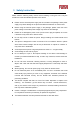
3 Safety Instruction Please read the following safety notices before installing or using this unit. They are crucial for the safe and reliable operation of the device. Please use the external power supply that is included in the package. Other power supply may cause damage to the phone and affect the behavior or induce noise. Before using the external power supply in the package, please check the home power voltage. Inaccurate power voltage may cause fire and damage.
4 Overview 4.1 Overview i53W is an indoor station with 7-inch color touch screen and rich interfaces. It is mainly used in residential area, villa, office building and other places for receiving calling and communicating through the door phone and achieving remote door-opening. It provides more reliable security assurance and the easier access control for the users, creating a safe and comfortable living environment.
5 Install Guide 5.1 Use PoE or external Power Adapter i53W supports two power supply modes, external power adapter and Ethernet (PoE) switch power supply mechanism PoE power supply saves the space and cost of providing the device additional power outlet. With a PoE switch, the device can be powered through a single Ethernet cable which is also used for data transmission.
Picture 1 - Peripheral connection diagram Picture 2 - interface Table 1- interface N0. ○1 Interface Description DC Power interface:12V/1A input. Ethernet interface: standard RJ45 interface, 10/100M ○2 adaptive, it is recommended to use CAT5 or CAT5E network cable. ○3 ○4 Industrial power interface 2 sets of RS485 interfaces: can be connected to card reader, sensor etc. 8 sets of alarm input interfaces: input devices for connecting ○5 switches, infrared sensor, door sensor, vibration sensors etc.
6 Appendix Table 6.
Connecting WIFI Wi-Fi network abnormal SIP Hotspot DND Missed call SMS Unread voice message Network storm Table 4- DSSkey Icons Icon Translate BLF/NEW CALL BLF/BXFER BLF/AXFER BLF/CONF BLF/DTMF Presence MWI Speed Dial Intercom 14
Call Park Call forward Key Event URL/Action URL BLF List Multicast Memory Key None None Line DTMF 15
6.2 Appendix II –Function key state definition Table 5-Look-up Table of Characters Type Line Key Icon State Gray Line is not configured Green On Line ready (Registered) Red Blinking Line is trying to register Red Blinking BLF Green On Red On Red On Off Presence Green On Red On Red On Off DND MWI Description Line error (Registration failure) Subscription number is idle. Subscription number is busy. Subscription number is dialing. Subscription number is unavailable.
7 User Getting Started 7.1 Button description Picture 3 - Key Description The picture above shows the button layout of the device. Each button provides its own specific function. The user can operate the device by referring to the description of the buttons in the illustrations in this section.
7.2 Introduction to the User 7.2.1 Standby interface Picture 4- Standby interface The figure above shows the default standby screen interface, which is the state of the user interface most of the time. The upper half of the main screen displays the welcome message, time and date, and status information (such as automatic answer, network connection status, etc.).
Picture 5-Menu interface Table 8- dial interface Number Features Description 1 Return key Return to the previous menu, the main interface 2 Dialpad Enter the dial interface 3 Contact Enter the contact interface, view/edit contacts 4 Call records Enter the call log interface, view the call log 5、6 Turn page 7 Home Back to main interface 8 Volume Down Key Volume Adjustment 9 Volume Up Key Volume Adjustment 10 Dial key After entering the number, press to call out 11 Numeric keypad
7.2.3 Commonly used icons on the interface Introduction to icons commonly used by equipment. Table 9- Commonly used icons Icon Description Back to Icon Description main Previous page interface Next page Return Search for Add to contacts Save 7.3 Use of touch keyboard The device supports using the touch keyboard to enter data.
right 8 9 Delete Delete entered characters Next Switch to the next edit box Done Save operation 10 Hide keyboard Tap on the screen to switch to number and special character input mode. Picture 7 - Keyboard numbers & characters Table 11 - Keyboard numbers & characters Number Function keys Description 1 Number Key Type in data 2 3 Switch to special character input mode Switch lowercase English letter input mode 7.
System Running Time SIP Account Information: SIP Account SIP Account Status (registered / uncommitted / trying / time out) TR069 Connection Status(Displays only in the phone interface state) The user can view the phone status through the phone interface and the web interface. Device interface: When the device is in standby, press [Menu] >> [Status], select options to view corresponding information, as shown in the figure: Picture 8- keyboard WEB interface:Refer to 7.
Picture 9- phone status 7.5 Web Management Phone can be configured and managed on the web page of the phone. The user needs to enter the IP address of the phone in the browser at first and open the web page of the phone. The user can check the IP address of the phone by pressing [Menu] >> [Status]. Picture 10- Login page Users must correctly enter the user name and password to log in to the web page. The default user name and password are "admin".
7.6 Network Configurations The i53W device supports two network connection methods: wired network connection and wireless network connection. Users need to choose the corresponding connection method according to their own situation. The device uses an IP network connection to provide services. Unlike traditional devices based on line circuit technology, IP devices are connected to each other through the network to exchange data packets and data based on the device's IP address.
for most users. Static IP configuration – This option allows users to manually configure each IP parameter, including IP address, mask, gateway, and primary and secondary domain names. This usually applies to some professional network user environments. For specific configuration and use, please refer to 10.6.2.1 Network Settings and 10.5 WiFi 7.7 SIP Configurations A line must be configured properly to be able to provide telephony service. The line configuration is like a virtualized SIM card.
Picture 11- Web Line Registration 26
8 Basic Function 8.1 Making Phone Calls Default Line The equipment provides 6 SIP line services. If all the 6 lines are configured successfully, the user can use any line to make or receive calls. If the user has set a default line, the number or name currently used by default will be displayed in the upper left corner of the screen interface.
cancel the call Picture 13- Call interface 8.2 Answer a call When the device is idle and there is an incoming call, the user will see the following call reminder screen. Picture 14- Voice call interface The user can answer the call by pressing the button or the interface. To reject an incoming call, the user presses or the reject button on the interface. 8.
Picture 15- Taking interface Table 12 - Taking mode Number The keypad names Instruction 1 Contact Name The name of the other party 2 Contact Number Call the other party's number 3 Call duration Call duration 4 Mute icon Icon indication after the call is muted 5 6 7、8 Voice quality, HD, voice encryption End Display the current call voice quality, voice call encryption and other icon indicators Hang up Volume addition and subtraction Adjust call volume 8.
Picture 16- Web page configuration DTMF 8.5 End of call Picture 17- Call end interface When the user's call ends 1) You can press to end the call 2) You can press to end the call 3) You can press the end button on the call interface 8.
In standby, press the shortcut key set on the right side of the standby interface. Picture 19- Webpage configuration standby interface preview Picture 20- Standby interface display after configuration 8.7 Dial query The device defaults to enable the dial query function, open the dial pad to dial, enter one or more numbers, the dial interface will automatically match the call record, the number list in the contact, click to select the number and call out. 8.
on/off the auto answer option, set the auto answer time, the default is 5 seconds Press to save when finished The icon in the upper right corner of the screen indicates that auto answer is enabled. Picture 21 - Line 1 enables auto-answering Web interface : Log into the device webpage, enter [Line]>>[SIP], Select [Basic Settings], enabled automatic answering, set the automatic answering time and click submit.
8.9 Mute You can turn on the silent mode and turn off the microphone of the device during a call, so that the other party cannot hear the local voice. Under normal circumstances, the silent mode is automatically turned off as the call ends. You can also enable the keep mute function on any interface (such as the idle interface) to automatically mute the ringtone when a call comes in. 8.9.
to and there is no ringtone. After hanging up, the device will still ring the next time there is an incoming call. Picture 24 - Ringing mute 8.10 DND User may enable Do-Not-Disturb (DND) feature on the device to reject incoming calls (including call waiting). The DND can be enabled on line basis.
Picture 25- DND setting interface Users can also use the Do Not Disturb timer. After setting, within the time range, the Do Not Disturb function will be automatically turned on and the DND icon will turn red Picture 26- DND timer Web interface: Go to [Settings] >> [Function Settings] >> [DND Settings], set the type of DND (off, phone, line), and DND timing function.
The user opens the DND of a specific line on the webpage: enter [Line] >> [SIP] >> [Basic Settings], and enable DND. Picture 28 - Line DND 8.11 Call Forward Call forward is also known as ‘Call Divert’ which is to divert the incoming call to a specific number based on the conditions and configurations. User can configure the call forward settings of each line. There are two types, Unconditional Call Forward – Forward any incoming call to the configured number.
Picture 29- Set call forward Web interface: Enter [Line] >> [SIP]>> [Basic Settings], and set the forward type, number, and time.
9 Advance Function 9.1 Intercom After the device enables intercom, it can automatically answer intercom calls. Picture 31- Web Intercom configure Table 13 - Intercom configure Parameter Description Enable Intercom When intercom is enabled, the device will accept the incoming call request with a SIP header of Alert-Info instruction to automatically answer the call after specific delay.
user to send a Real Time Transport Protocol (RTP) stream to the pre-configured multicast address without involving SIP signaling. You can also configure the phone to receive an RTP stream from pre-configured multicast listening address without involving SIP signaling. You can specify up to 10 multicast listening addresses.
Receiver will receive multicast call and play multicast automatically. Dynamic multicast: Function description: Send multicast configuration information through Sip Notify signaling. After receiving the information, the device configures it in the system for multicast monitoring or cancels multicast monitoring in the system 9.3 SMS 9.3.
9.3.2 MWI(Message Waiting Indicator) If the service of the lines supports voice message feature, when the user is not available to answer the call, the caller can leave a voice message on the server to the user. User will receive voice message notification from the server and device will prompt a voice message waiting icon on the standby screen. Picture 34- New Voice Message Notification -To listen to a voice message, the user must first configure the voicemail number.
Picture 35 - Voice message interface 9.4 SIP Hotspot SIP hotspot is a simple but practical function. With simple configurations, the SIP hotspot function can implement group ringing. SIP accounts can be expanded. Set a phone as a SIP hotspot and other phones (B and C) as SIP hotspot clients. When somebody calls phone A, phone A, B, and C all ring. When any phone answers the call, other phones stop ringing. The call can be answered by only one phone.
Table 15- SIP hotspot Parameters Parameters Description If your phone is set to “SIP hotspot server”, Device Table will display as Client Device Table SIP hotspot Enable hotspot Mode Monitor Type Monitor Address Remote Port Device Table which connected to your phone. If your phone is set to “SIP hotspot client”, Device Table will display as Server Device Table which you can connect to. Set it to be Enable to enable the feature.
Picture 38- SIP hotspot client configuration As the hotspot server, the default extension number is 0. When the phone is used as the client, the extension number is increased from 1, you can view the extension number through the [SIP Hotspot] page. Call extension number: The hotspot server and the client can dial each other through the extension number. For example, extension 1 dials extension 0.
10 Phone Settings 10.1 10.1.1 Basic Settings Language The user can set the phone language through the phone interface or web interface. Phone interface : After resetting the factory settings, the user needs to set the language; when setting the language during standby, go to [Menu] >> [Basic Setting] >>[UI Preference]>> [Language] Settings, as shown in the figure.
Picture 40- web page language setting The function box on the right side of the web interface language setting box is “Synchronize language to phone”; if selected, the phone language will be synchronized with the webpage language. If it is not selected, it will not be synchronized. 10.1.2 Time & Date Users can set the phone time through the phone interface and web interface.
Picture 41 set time & date Web end: Log in to the phone webpage and enter [Phone Settings] >> [Time/Date] , as shown in the figure: Picture 42- webpage set time &date Table 15- set time Parameters Parameters Description Mode Auto/Manual Auto: Enable network time synchronization via SNTP protocol, default enabled. Manual: User can modify data manually.
MM-DD-YYYY YY-MM-DD YYYY-MM-DD Separator Choose the separator between year and moth and day 12-Hour Clock Display the clock in 12-hour format Daylight Saving Time Enable or Disable the Daylight Saving Time 10.1.3 Screen The user can adjust the brightness of phone screen in LCD in two ways. Slide down the outgoing status bar page in standby mode. Slide down again to adjust phone brightness conveniently.
10.1.3.1 Brightness and backlight Set the brightness level in the use state from 1 to 16. Set the brightness level in energy saving mode from 0 to 16 optional. Set the backlight time, the default is 30 seconds, you can turn it off or choose 15 seconds/30 seconds/45 seconds/60 seconds/90 seconds/120 seconds. The screen saver can be turned on or off, and it is turned on by default. Web interface: Enter [Settings] >> [Advanced], edit the screen parameters, and click Submit to save.
Picture 45- Screensaver 10.1.4 Ring When the device is in the default standby mode, Enter [Menu] >> [Basic settings]. Enter [Ring&Tone] >> [Ring] Set ring type and save it by press 10.1.5 Voice Volume When the device is in the default standby mode Enter [Menu] >> [Basic settings]. Enter [Ring&Tone] >> [Voice Volume] Set volume and save it by press 10.1.6 。 Greeting words The device is in the default standby state. Press [Menu] to find the [Basic Settings] button.
Enter the setting interface, press to save after completion Note: Only after the default line selection function is disabled, the welcome message can be displayed in the upper left corner of the standby 10.1.7 Reboot When the device is in the default standby mode, Enter [Menu] >> [Basic setting] >> [Reboot] item. Click [Reboot] to indicate whether to restart the phone. Press to restart the phone or press to exit the prompt box to return to the configuration interface. 10.
When there are contact records in the phone book, the contact records will be arranged in the alphabet order. User may browse the contacts with up/down navigator keys. The record indicator tells user which contact is currently focused. User may check the contact’s information by pressing [OK] button. 10.2.1.1 Add / Edit / Delete Contact Add a contact, click to enter the contact interface, select the first icon (contact icon, selected by default) and add the following contact information.
Picture 48- edit contact Delete the contact, press whether to delete, press 10.2.1.2 to delete the contact, when press it will prompt to delete. Add / Edit / Delete Group By default, the group list is empty. Users can create their own group, edit group names, add or remove contacts from the group, and delete groups. Add group. Enter contact list interface, press Delete groups, press To edit the group, press to create groups. to delete to edit.
Picture 49- group 10.2.1.
synchronized to the local phone book. You can also delete contacts in the group by press . 10.2.2 Black list The device supports blacklist, such as the number added to the blacklist, the number of calls directly refused to the end, the end of the phone shows no incoming calls. (Blacklisted Numbers can be called out normally) There are multiple ways to add a number to Blacklist on the device. It can be added directly on [Menu] >> [phone book] icon>> [Black list].
Picture 52- Black list 10.2.3 Cloud Phone Book 10.2.3.1 Configure Cloud Phone book Cloud phonebook allows user to configure the device by downloading a phonebook from a cloud server. This is convenient for office users to use the phonebook from a single source and save the effort to create and maintain the contact list individually.
Picture 53 - cloud contacts 10.2.3.2 Downloading Cloud Phone book In cloud phone book screen, user can open a cloud phone book by pressing the network phonebook. The device will start downloading the phone book. The user will be prompted with a warning message if the download fails, Once the cloud phone book is downloaded completely, the user can browse the contact list and dial the contact number same as in local phonebook.
Picture 54-Browsing Contacts in Cloud Phone book 10.3 Call Log The device can store up to 1000 call log records and user can open the call logs to check all incoming, outgoing, and missed call records by pressing [CallLog] icon. In the call logs screen, user may browse the call logs with up/down navigator keys. Each call log record is presented with ‘call type’ and ‘call party number / name’.
- Missed Call Log - Incoming Call Log - Outgoing Call Log - Forward Call Log Picture 56- Filter call record types 10.4 Function Key It shows 8 DSSKEY keys in standby mode on Screen, each of which can be customized.
Picture 57- Dss key settings The DSS Key could be configured as followings, Memory Key Speed Dial/Intercom/BLF/Presence/Call Park/Call Forward (to someone) Line Key Event MWI/DND/Hold/Transfer/Phonebook/Redial/Pickup/Call Forward (to specified line)/Headset/ SMS/Release DTMF Action URL BLF List Key MCAST Paging MCAST Listening Action URL XML Browser Moreover, user also can add the user-defined title for the DSS Keys, which is configured as Memory Key / Line / U
10.5 Wi-Fi The device supports wireless Internet access and has built-in Wi-Fi without external devices. 10.5.1 Wireless network When the device is in the default standby state, search for wireless networks Press menu [Menu] >> [Basic Settings] . Click [Basic Settings] >> [WLAN]. Click [Wireless Network] to enter the setting interface. Turn on the wireless network, click Save, and the device will automatically search for wireless networks under the current network after enabling.
Picture 59-wireless network Connection to wireless network Log in to the webpage, [Network]>>[Wi-Fi Settings] Configure Wi-Fi information, after the configuration is complete, click Add Turn on Wi-Fi and click Submit.
10.5.2 AP setting In the absence of a wired network, you can set up a wireless network connection by turning on the AP mode of the device and connecting to the backstage webpage of the device with a mobile phone. Press menu button [Menu] >> [Basic Settings] button.
After the connection is successful, scan the QR code with the browser of the mobile phone to enter the login interface of the device background Enter username/password (default admin) After logging in, select Wi-Fi settings, manually add Wi-Fi and enable Wi-Fi, the device will automatically connect to the Wi-Fi network after the setting is completed Back to standby, you can see the Wi-Fi icon in the status bar 10.6 10.6.
Picture 63- Configure Advanced Line Options 10.6.1.1 Network Settings 10.6.1.2 Network Settings Phone access [Phone Settings] >> [Network] >> [Network], you can configure the SIP line on the phone.
Picture 64- IP Mode IPv4 The network type has three modes: DHCP, PPPoE, and static IP. Picture 65- DHCP network mode When using DHCP mode, phone will get the IP address from DHCP server (router).
Obtain DNS Server automatically: It is enabled as default. “Enable” means phone will get DNS address from DHCP server and “disable” means not. Picture 66 - PPPoE network mode When the network is set to PPPoE, the PPPoE server issues the network IP address of the device. User: Fill in the username of the PPPoE server.
When using Static IP mode, user must configure the IP address manually. IP Address:Phone IP address. Subnet Mask: sub mask of your LAN. IP Gateway:The gateway IP address. Phone could access the other network via it. Primary DNS : Primary DNS address. The default is 8.8.8.8, Google DNS server address. Secondary DNS:Secondary DNS. When primary DNS is not available, it will work. IPv6 The network type has two modes to : DHCP and static IP.
segment. Phone could use LLDP to find the VLAN switch or other VLAN devices and use LLDP to learn feature to apply the VLAN ID from VLAN switch to phone its self. CDP Cisco Discovery Protocol. CDP is a not-for-profit charity that runs the global disclosure system for investors, companies, cities, states and regions to manage their environmental impacts. According to the CDP, Cisco devices could share the OS version, IP address, hardware version and so on.
Layer 2 Transportation Protocol (L2TP) and OpenVPN. The VPN connection must be configured and started (or stopped) from the device web portal. L2TP NOTICE! The device only supports non-encrypted basic authentication and non-encrypted data tunneling. For users who need data encryption, please use OpenVPN instead. To establish a L2TP connection, users should log in to the device web portal, open page [Network] -> [VPN].
Same as L2TP connection, the connection will be established every time when system rebooted until user disable it manually. http://www.fanvil.com/Uploads/Temp/download/20180920/5ba38303bfcf0.pdf 10.6.1.5 Web Server Type Configure the Web Server mode to be HTTP or HTTPS and will be activated after the reboot. Then user could use http/https protocol to access pone web page. Picture 69 - The phone configures the web server type 10.6.
Picture 70- Menu Password Picture 71 - Menu password setting The menu password is the advanced setting password. [Current password] If you not set password, the default password is 123. [New password] The password you want to reset. The password immediately takes effect after the setting is completed, and the password is not displayed in plain text after being entered.
Picture 72- Menu password input The keyboard password is used to unlock the keyboard after the device is locked. Picture 73- keyboard password setting The setting of keyboard password only for turn on or turn off on device Select [Keyboard Password] and click it ,it will pop up a prompt to enter a password, this password is the menu password (the default password is 123 ).
If the password is correct, you will enter the keyboard lock status interface. The keyboard lock status is off by default, and the timeout period will take effect after you choose to enable it. Return to standby.,After the timeout period, the device will lock the keyboard, and there will be a lock icon on the top of the device. Press any key at this time will prompt a password box. Picture 74- webpage keyboard password setting 10.6.
Picture 75- Page auto provision Settings LCD:Enter [Phone Settings] >> [System] >> [Maintain] >> [Auto Provision]. Picture 76- Phone auto provision settings Fanvil devices support SIP PnP, DHCP options, Static provision, TR069. Transferring protocol: FTP、 TFTP、 HTTP、 HTTPS Details refer to Fanvil Auto Provision in http://www.fanvil.com/Uploads/Temp/download/20180920/5ba3816f8d5f0.
Parameters Description Basic settings CPE Serial Number Display the device SN Authentication Name The user name of provision server Authentication Password The password of provision server Configuration File If the device configuration file is encrypted , user should add Encryption Key the encryption key here General Configuration File If the common configuration file is encrypted, user should add Encryption Key the encryption key here Download Fail Check If there download is failed, phone
Static Provisioning Server Server Address Provisioning server address. Support both IP address and domain address. The configuration file name. If it is empty, phone will request the common file and device file which is named as its MAC Configuration File Name address. The file name could be a common name, $mac.cfg, $input.cfg. The file format supports CFG/TXT/XML. Protocol Type Update Interval Transferring protocol type ,supports FTP、TFTP、HTTP and HTTPS Configuration file update interval time.
Picture 77- Web page firmware upgrade LCD interface: go to [Menu] >> [Maintain] >> [Upgrade] . Table 18- firmware upgrade Parameter Description Upgrade server Enable automatic upgrade, If there is a new version txt Enable Auto Upgrade and new software firmware on the server, phone will show a prompt upgrade message after Update Interval. Upgrade Server Address1 Set available upgrade server address. Upgrade Server Address2 Set available upgrade server address. Update Interval Set Update Interval.
The file requested from the server is a TXT file called vendor_model_hw10.txt.Hw followed by the hardware version number, it will be written as hw10 if no difference on hardware. All Spaces in the filename are replaced by underline. The URL requested by the phone is HTTP:// server address/vendor_Model_hw10 .txt : The new version and the requested file should be placed in the download directory of the HTTP server, as shown in the figure: TXT file format must be UTF-8 vendor_model_hw10.
Picture 78- firmware upgrade 10.6.5 Factory Reset The phone is in default standby mode. Press [Phone Settings] to find [System]>> [Maintain]>> [ Phone Reset]. Press the [Reset] button to select the file to be cleared. Press [OK] to clear after completion. When you select clear configuration file and clear all, the phone will restart automatically after clearing.
11 Web Configurations 11.1 Web Page Authentication The user can log into the web page of the phone to manage the user's phone information and operate the phone. Users must provide the correct user name and password to log in. When logging in to the web page with the same or different IP,if the user name/password is entered incorrectly three times, the web page will be locked and you can log in again. after 5 minutes.
When the user logs in for the first time, the default user name and password are used. If the password is not changed after login, the web page will prompt "The default password is being used, please change it". After clicking, you can jump to the modify password interface to modify the login password. Picture 81- default password prompt 11.
11.4 System >> Configurations On this page, users with administrator privileges can view, export, or import the phone configuration, or restore the phone to factory Settings. Clear Configurations Select the module in the configuration file to clear. SIP: account configuration. AUTOPROVISION: automatically upgrades the configuration TR069:TR069 related configuration MMI: MMI module, including authentication user information, web access protocol, etc.
11.8 System >> Reboot Phone This page can restart the phone. 11.9 Network >> Basic This page allows users to configure network connection types and parameters. Picture 82- Network settings Network priority: When wired and wireless are enabled at the same time, you can choose to use wired or wireless first. Network type: you can view the information of wired/wireless network 11.10 Network >> Service Port This page provides settings for Web page login protocol, protocol port settings and RTP port.
Picture 83- Service Port Settings Table 19 - Service port Parameter Description Web Server Type Reboot to take effect after settings. Optionally, the web page login is HTTP/HTTPS. Web Logon Timeout Default as 15 minutes, the timeout will automatically exit the login page, need to login again. Web auto login After the timeout does not need to enter a user name password, will automatically login to the web page. HTTP Port The default is 80.
and get more details. 11.12 Line >> SIP Configure the Line service configuration on this page. Table 20- Line configuration on the web page Parameters Description Register Settings Line Status Display the current line status at page loading. To get the up to date line status, user has to refresh the page manually. Activate Whether the service of the line is activated Username Enter the username of the service account.
Proxy Server Port Enter the SIP proxy server port, default is 5060. Proxy User Enter the SIP proxy user. Proxy Password Enter the SIP proxy password. Backup Proxy Server Address Enter the IP or FQDN address of the backup proxy server. Backup Proxy Server Port Enter the backup proxy server port, default is 5060.
voice message waiting on the server Voice Message Number Set the number for retrieving voice message Voice Message Subscribe Period Set the interval of voice message notification subscription Enable Hotline Enable hotline configuration, the device will dial to the specific number immediately at audio channel opened by off-hook handset or turn on hands-free speaker or headphone Hotline Delay Set the delay for hotline before the system automatically dialed it Hotline Number Set the hotline dialing nu
Advanced Settings Use Feature Code When this setting is enabled, the features in this section will not be handled by the device itself but by the server instead. In order to control the enabling of the features, the device will send feature code to the server by dialing the number specified in each feature code field.
of BLF phone. Please enter the BLF server, if the sever does not support subscription package, the registered server and subscription server will be separated.
Sync Clock Time Time Sync with server Enable Inactive Hold With the post-call hold capture package enabled, you can see that in the INVITE package, SDP is inactive. Caller ID Header Set the Caller ID Header Use 182 Response for Call waiting Set the device to use 182 response code at call waiting response Enable Feature Sync Feature Sync with server Enable SCA Enable/Disable SCA (Shared Call Appearance ) CallPark Number Set the CallPark number.
Enable Group Set open group. Enable RFC4475 Set to enable RFC4475. Enable Strict UA Match Enable strict UA matching. Registration Failure Retry Time Set the registration failure retry time. Local SIP Port Modify the phone SIP port. Enable uaCSTA Set to enable the uaCSTA function. 11.13 Line >> SIP Hotspot Please refer to 9.4 SIP Hotspot. 11.
Attended Transfer on Onhook Hang up the handle or press the hands-free button to realize the function of attention -transfer, which can transfer the current call to a third party. Attended Transfer on Conference Onhook During a three-way call, hang up the handle and the remaining two parties remain on the call. Enable E.164 Please refer to e.
by commas, or a list of digits. Destination Set Destination address. This is for IP direct. Port Set the Signal port, and the default is 5060 for SIP. Alias Set the Alias. This is the text to be added, replaced or deleted. It is an optional item. Note: There are four types of aliases. all: xxx – xxx will replace the phone number. add: xxx – xxx will be dialed before any phone number. del –The characters will be deleted from the phone number.
Picture 87- Dial rules table (2) Example 3: Addition -- Two examples are shown. In the first case, it is assumed that 0 must be dialed before any 11 digit number beginning with 13. In the second case, it is assumed that 0 must be dialed before any 11 digit number beginning with 135, 136, 137, 138, or 139. Two different special characters are used. x -- Matches any single digit that is dialed. [] -- Specifies a range of numbers to be matched.
Parameters Description STUN Settings Server Address Set the STUN server address Server Port Set the STUN server port, default is 3478 Binding Period Set the STUN binding period which can be used to keep the NAT pinhole opened. SIP Waiting Time Set the timeout of STUN binding before sending SIP messages Certification File TLS Certification File Upload or delete the TLS certification file used for encrypted SIP transmission. 11.17 Settings >> Features Configuration phone features.
Enable Silent Mode When enabled, the phone is muted, there is no ringing when calls, you can use the volume keys and mute key to unmute. Disable Mute for Ring When it is enabled, you can’t mute the phone Enable Default Line If enabled, user can assign default SIP line for dialing out rather than SIP1.
Push XML Server Configure the Push XML Server, when phone receives request, it will determine whether to display corresponding content on the phone which sent by the specified server or not. Enable Pre-Dial Disable this feature, user enter number will open audio channel automatically. Enable the feature, user enter the number without opening audio channel.
the incoming call request with a SIP header of Alert-Info instruction to automatically answer the call after specific delay. Enable Intercom Mute Enable mute mode during the intercom call Enable Intercom Tone If the incoming call is intercom call, the phone plays the intercom tone Enable Intercom Barge Enable Intercom Barge by selecting it, the phone auto answers the intercom call during a call.
off, on is always red bright, the default is off. Power lamp status when there is an incoming Ringing call, including off/on/slow flash/quick flash, default flash. Power lamp status in mute mode, including Mute off/on/slow flash/quick flash, off by default. The power lamp state, including off/on/slow Hold/Held flash/quick flash, is turned off by default when left/retained.
G.726-16,G726-24,G726-32,G.726-40, ILBC,opus Video codec Video codec Select to enable video encoding:H264 Media Setting DTMF Payload Type Enter the DTMF payload type, the value must be 96~127. Headset Mic Gain Set the earphone's radio volume gain to fit different models of earphones. Opus playload type Set Opus load type, range 96~127. Set Opus sampling rate, including opus-nb (8KHz) OPUS Sample Rate and opus-wb (16KHz). ILBC Payload Type Set the ILBC Payload Type, the value must be 96~127.
11.19 Settings >> MCAST This feature allows user to make some kind of broadcast call to people who are in multicast group. User can configure a multicast DSS Key on the phone, which allows user to send a Real Time Transport Protocol (RTP) stream to the pre-configured multicast address without involving SIP signaling. You can also configure the phone to receive an RTP stream from pre-configured multicast listening address without involving SIP signaling.
Secondary Time Server Set secondary time server address, when primary server is not reachable, the device will try to connect to secondary time server to get time synchronization.
Repetition period Do not repeat: execute once within the set time range Daily: Perform this operation in the same time every day Weekly: Perform this operation in the same time of the week Monthly: Perform this operation in the same time of the Month Effective time Set the operation time Forward Number Set the SIP number for forwarding in the time range Line Set the line for forwarding in the time range Picture 88- time plan 11.23 Settings >> Tone This page allows users to configure a phone prompt.
Picture 89- Webpage Tone 11.24 Settings >> Advanced User can configure the advanced configuration settings in this page. Screen Configuration. Enable Energy Saving Backlight Time Screen Saver LCD Menu Password Settings. Configure Greeting Words The greeting message will display on the top left corner of the LCD when the device is idle, which is limited to 16 characters. The default chars are ‘Indoor Station’. 11.
be copied to the contact edit boxes, press “Modify” button after finished editing. To delete one or multiple contacts, check on the checkbox in front of the contacts wished to be deleted and click the “Delete” button, or click the “Clear” button with selecting any contacts to clear the phonebook.
Access password (optional) Note! Refer to the LDAP technical documentation before creating the LDAP phonebook and phonebook server. Web page preview Phone page supports preview of Internet phone directory and contacts After setting up the XML Voip directory or LDAP, Select [Phone book] >> [Cloud phone book] >> [Cloud phone book] to select the type. Click the set XML/LDAP to download the contact for browsing. Picture 90- Web cloud phone book Settings 11.
removed from the table. 11.28 Phonebook >> Web Dial Use web pages for call, reply, and hang up operations. 11.29 Phonebook >> Advanced Users can export the local phone book in XML, CSV, and VCF format and save it on the local computer. Users can also import contacts into the phone book in XML, CSV, and VCF formats. Attention! If the user imports the same phone book repeatedly, the same contact will be ignored. If the name is the same but the number is different, the contact is created again.
One-key transfer Settings: establish new call, blind transfer, attention-transfer, one-key three-party, Play DTMF. DSS Key home page: None/Page1/Page2/Page3/Page4 The device provides 112 user-defined shortcuts that users can configure on a web page. Parameters Description Memory Key BLF (NEW CALL/BXFE /AXFER): It is used to prompt user the state of the subscribe extension, and it can also pick up the subscribed number, which help user monitor the state of subscribe extension (idle, ringing, a call).
page. For Side Key ,please refer to 11.31 function key。 11.33 Function Key >> Softkey The User Settings mode and display style, display page.
Redial/Delete/Exit/2aB/Dial/Local Contacts/Transfer/ Transfer Dialer CallLog/Clear/Missed/Dialed/Pause/Headset/Video/Audio/R emote XML/DSS Key Trying End/Release/Headset/DSS Key Hold/Transfer/Conference/End/Answer/Forward/Mute/Next Waiting call/New call/Prev call/Reject/Release/Headset/Listen/ Video/Audio/DSS Key 11.34 Function Key >> Advanced IP Camera List Support to discover the IP Camera in local area network.
Picture 92- Web Filter settings Picture 93- Web Filter Table Add and remove IP segments that are accessible; Configure the starting IP address within the start IP, end the IP address within the end IP, and click [Add] to submit to take effect. A large network segment can be set, or it can be divided into several network segments to add. When deleting, select the initial IP of the network segment to be deleted from the drop-down menu, and then click [Delete] to take effect.
Picture 94- Certificate of settings 11.37 Security >> Device Certificates Select the device certificate as the default and custom certificate. You can upload and delete uploaded certificates. Picture 95 - Device certificate setting 11.38 Device Log >> Device Log You can grab the device log, and when you encounter an abnormal problem, you can send the log to the technician to locate the problem. See 11.6 Get log information.
11.39 Security Settings Picture 96- Input and output settings Security Settings parameter description Basic Settings Ringtone Duration The duration of the alarm bell Configure the remote response server address (including the remote Input & response server address and the alarm trigger server address).
12 Trouble Shooting When the phone is not in normal use, the user can try the following methods to restore normal operation of the phone or collect relevant information and send a problem report to Fanvil technical support mailbox. 12.1 Get Device System Information Users can get information by pressing the [Menu] >> [Status] option in the phone.The following information will be provided: The network information Equipment information (model, software and hardware version), etc. 12.
Picture 97- Input and output settings 12.5 Network Packets Capture Sometimes it is helpful to dump the network packets of the device for issue identification. To get the packets dump of the device, user needs to log in the device web portal, open page [System] >> [Tools] and click [Start] in “Packets Capture” section. A pop-up message will be prompt to ask user to save the capture file.
Picture 98- Web capture User may examine the packets with a packet analyzer or send it to Fanvil support mailbox. 12.6 Get Log Information Log information is helpful when encountering an exception problem.
contact your service provider to get support, or follow the instructions in “12.5 Network Packet Capture” to get the network packet capture of registration process and send it to Fanvil support to analyze the issue.