H5_Hotel Phone User Manual_V1.
Document VER Firmware VER Explanation Time V1.0 2.0.2.2770 Initial issue 20161130 V1.1 2.0.2.
Table of Content Figures................................................................................................................................................................................... 5 Tables..................................................................................................................................................................................... 5 1 Safety Instruction................................................................................................
8.9 NETWORK / Advanced................................................................................................................................... 21 8.10 NETWORK / VPN............................................................................................................................................21 8.11 LINES / SIP.......................................................................................................................................................21 8.12 LINES / Dial Peer..
Figures Figure 1 - Device to Connection................................................................................................................ 10 Figure 2 - Keypad........................................................................................................................................... 11 Figure 3 - The Web Login page ................................................................................................................ 14 Figure 4 - Memory Key Setting...............
Tables Table 1 - SIP Settings for Lines on Web.................................................................................................. 22 Table 2 - Dial Peer Settings for Lines on Web........................................................................................25 Table 3 - Global Settings for Lines on Web............................................................................................ 29 Table 4 - Common Phone Feature Settings on Web.....................................
1 Safety Instruction Please read the following safety notices before installing or using this unit. They are crucial for the safe and reliable operation of the device. Please use the external power supply that is included in the package. Other power supply may cause damage to the phone, affect the behavior or induce noise. Before using the external power supply in the package, please check the home power voltage. Inaccurate power voltage may cause fire and damage.
2 Overview H5 is newest series of phonesdesigned for hotels. Its stylish, contemporary appearance, excellent voice quality and powerful functionality, along with matching integrated communications platforms can replace traditional phones and can become a new generation of intelligent terminal equipment.The H-Series hotel IP phone will look great in most hotel rooms andwill support most application requirements.In addition, it has excellent call quality.
3 Installation 3.1 Use PoE or external Power Adapter H5, called as ‘the device’ hereafter, supports two power supply modes, power supply from external power adapter and supports 802.3af Class 2 Power over Ethernet (PoE) complied switch. PoE power supply saves the space and cost of providing the device additional power outlet. With a PoE switch, the device can be powered through a single Ethernet cable which is also used for data transmission.
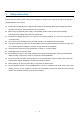
3.2 Connection methods Please connect power adapter, network, PC, and handset to the corresponding ports as described in below picture.
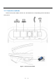
4 Introduction to the Phone User Interface 4.1 Keypad 3.5inch color screen DSS Key Message waiting / Speaker Incoming call indicator Volume Control Hold Mute Call forward Speaker Redial MWI Figure 2 - Keypad The above picture shows the keypad layout of the device. Each key provides its own specific function. User should refer to the illustration in this section about the usage of each key and the description in this document about each function.
lower/increase the audio volume.
5 Phone Settings In order to get the device ready for making and receiving phone calls, the device must be configured with correct network configurations and at least one of the lines must be configured with an SIP telephony service. The SIP must be configured properly to be able to provide telephony service. 5.1 Getting IP address DHCP is the default setting in Network, and telephone will get the IP address from DHCP server(Router) after the line connected. There are three common IP configuration modes.
Figure 3 - The Web Login page 5.4 SIP Setting Enter into the web setting interface, select Line->SIP, and fill in the items below. Server Address Account Name Phone Number Password Click the Apply button to save the config, you can dial out after the Register Status is Registered with red color. 5.5 Memory key setting Enter into the web setting interface, select Function key->Function key. Select the function and fill in the number in the value items.
6 Basic Operation 6.1 Making call SIP Line The device provides 1 line services.If lines are configured, user can make or receive phone calls on either line. Figure 5 - SIP Line Dialing Methods There are two ways to make a call, using dial pad or memory button. Lift the handset or press hands-free key. Dial the number on the dial pad or press memory key, end with # as default. End a call, hang up handset. 6.
User can answer the call by lifting the handset, or speaker phone by pressing the hands-free button. To divert the incoming call, user should press [forward] button. 6.3 Talking When the call is connected, user will see a talking mode screen as the following figure. Figure 7 - Talking Mode Screen 1.Audio Channel – The icon reflects the current audio channel being used. 2.Current Line – The line is being used on the call. 3.Remote Party – The name or number of the remote party. 4.
6.5 Call Ended When user finished the call, user can put the handset back to the device to hang up the call or press the hands-free button to close the audio channel to hang up. NOTICE! When the call is held or in holding state, the user must press [Resume] button to back to call mode, again putting the handset back to the device or pressing Speaker-free button to hang up is not available. 6.6 Redial Press redial to dial the last number you dialed. Lift handset or hands-free key.
7 Advance Operation 7.1 Call transfer Blind transfer During a call, you want to transfer the call to another one without talking. Press Transfer key, get the second dial tone , and the first call held automatically. Dial the number which you want to transfer to, and then press # button. You will hear the busy tone, the call have been transferred successfully. Figure 10 - Blind transfer Screen Attended transfer During a call, you want to transfer the call to another one after talking.
Figure 12 - Attended transfer Screen② 7.2 Messages waiting When the messages waiting lights up, you need to dial the feature access code for message retrieving. Once the messages have been retrieved, the lights up will stop. You can save your messages waiting feature access code on a memory button, when labeled Messages.
8 Web Portal 8.1 Web Portal Authentication User can log in onto the device web portal to manage the device or user’s profile. User must provide correct username and password to be able to log in. 8.2 SYSTEM / Information User can get the system information of the device in this page including.
8.4 SYSTEM / Configurations Users with Administrators privilege can export or import the device configuration in this page and reset the device to factory default. 8.5 SYSTEM / Upgrade The device supports online upgrade by periodically checking the software release version on the cloud server. Meanwhile, user can download the software and upgrade the device manually when there is trouble for the device to connect to the cloud server. 8.
Table 1 - SIP Settings for Lines on Web Parameters Description Basic Settings Line Status Display the current line status at page loading. To get the up to date line status, user has to refresh the page manually. Username Enter the username of the service account. Display Name Enter the display name to be sent in a call request.
Hotline Delay Enable Auto Answering Auto Answering Delay Set the delay for hotline before the system automatically dialed it Enable auto-answering, the incoming calls will be answered automatically after the delay time Set the delay for incoming call before the system automatically answered it Enable the device to subscribe a voice message waiting Subscribe For Voice Message notification, if enabled, the device will receive notification from the server if there is voice message waiting on the server Voi
Enable DND Set the feature code to dial to the server Disable DND Set the feature code to dial to the server Enable Call Forward Unconditional Disable Call Forward Unconditional Set the feature code to dial to the server Set the feature code to dial to the server Enable Call Forward on Busy Set the feature code to dial to the server Disable Call Forward on Busy Set the feature code to dial to the server Enable Call Forward on No Answer Disable Call Forward on No Answer Enable Blocking Anonymous Ca
Set the line to enable call ending by session timer refreshment.
Note: Two different special characters are used. x -- Matches any single digit that is dialed. [ ] -- Specifies a range of numbers to be matched. It may be a range, a list of ranges separated by commas, or a list of digits. Destination Set Destination address. This is for IP direct. Port Set the Signal port, and the default is 5060 for SIP. Alias Set the Alias. This is the text to be added, replaced or deleted. It is an optional item. Note: There are four types of aliases.
Example 2: Local Substitution To dial a long distance call to Beijing requires dialing area code 010 before the local phone number. Using this feature 1 can be substituted for 010. For example, to call 62213123 would only require dialing 162213123 instead of 01062213123. Figure 14 - Local Substitution Configuration Example 3: Add Prefixes If the dialed number starts with the fixed prefix number, the phone will send out your dialed phone number adding prefix number automatically.
Example 4: Add Suffixes If the dialed number ends with the fixed suffix number, the phone will send out your dialed phone number adding suffix number automatically. For example, when users dial “1383322”, the device will send out “13833220088” . Figure 16 - Add Suffixes Configuration Example 5: Deletion If the dialed number ends with the fixed prefix number, the phone will send out your dialed phone number deleting prefix number automatically.
8.13 LINES / Dial Plan Figure 18 - Dial Plan Configuration The device supports 8 dialing modes: Press # to Send - Dial the desired number, and press # to send it to the server. Dial Fixed Length – Configure the fixed length to dial out Send after seconds – Number will be sent to the server after the specified time. Press # to Do Blind Transfer - Press # after entering the target number for the transfer. The phone will transfer the current call to the third party.
STUN Settings Server Address Set the STUN server address Server Port Set the STUN server port, default is 3478 Set the STUN binding period which can be used to keep the Binding Period NAT pinhole opened. SIP Waiting Time Set the timeout of STUN binding before sending SIP messages Upload or delete the TLS certification file used for encrypted TLS Certification File 8.15 SIP transmission.
Disable Mute for Ring Disable Mute for Ring When intercom is enabled, the device will accept the incoming call Enable Intercom request with a SIP header of Alert-Info instruction to automatically answer the call after specific delay.
during taking, default enabled. Play Dialing DTMF Tone Play DTMF tone on the device when user pressed a phone digits at dialing, default enabled. Change caller ID display priority. The default priority is “Phonebook” > Caller ID Display Priority “SIP Display Name” > “SIP URI”. User may select one of the options to change the desired caller ID display priority. Hotline Number Set the Hot line Number Hotline Delay Set the Hot line Delay time. Action URL URL for various actions performed by the phone.
busy tone, ring-back tone, etc. Handset Volume Default Ring Type Set the Handset volume, the value must be 1~9 Set the default ring type. If the caller ID of an incoming call was not configured with specific ring type, the default ring will be used.
8.18 PHONE / Time/Date User can configure the device time settings in this page.
B5 Note: The Logo file name must be "TITLE_LOGO. BMP", otherwise will upload failed. Figure 19 - Background Picture Screen Configuration Enable Energizing: Enable according to timeout after closing the back light. The default is to disable. Back light timeout time is 30 seconds by default. Keyboard Lock Settings The default password is 123. Redial Clean Set clear time, after a timeout, will clear redial records.
Font: “L” on behalf of the Large, “M” on behalf of the Middle, “S” on behalf of the Small. Custom Display(Dialing Rules) Equipment support four rows in Custom Display, the maximum support 65 characters in each row. Fill in the need to display the information on each row, and select the display format, font, color and then click the apply, you can see the corresponding information on the screen.
Table 8 - DSS Key Setting Parameters on Web Parameters Description BLF(NEW CALL/BXFE /AXFER): It is used to prompt user the state of the subscribe extension, and it can also pick up the subscribed number, which help user monitor the state of subscribe extension (idle, ringing, a call). There are 3 types for one-touch BLF transfer method. p.s. User should enter the pick-up number for specific BLF key to fulfill the pick-up operation.
9 Advanced Features 9.1 VPN Virtual Private Network (VPN) is a technology to allow device to create a tunneling connection to a server and becomes part of the server’s network. The network transmission of the device may be routed through the VPN server. For some users, especially enterprise users, a VPN connection might be required to be established before activate a line registration. The device supports two VPN modes, Layer 2 Transportation Protocol (L2TP) and OpenVPN.
User then upload these files to the device in the web page [Network] -> [VPN], Section OpenVPN Files. Then user should check “Enable VPN” and select “OpenVPN” in VPN Mode and click “Apply” to enable OpenVPN connection. Same as L2TP connection, the connection will be established every time when system rebooted until user disable it manually.
10 Trouble Shooting When the device does not work properly, users may try the following methods to recover the device or gather relative information and send an issue report to support. 10.1 Upgrade to the latest software Manufacturer will keep publishing software update to fix bugs and improve device features. The device will check for new software release on manufacturer cloud server automatically and periodically. 10.
10.4 Common Trouble Cases Table 9 - Trouble Cases Trouble Case Solution 1. The device is powered by external power supply via power Device could not boot up adapter or PoE switch. Please use standard power adapter provided or PoE switch met with the specification requirements and check if device is well connected to power source 1. Please check if device is well connected to the network. The network Ethernet cable should be connected to the [Network] port NOT the [PC] port. 2.
Appendix I - Icon Illustration Table 10 - Keypad Icons Call Hold Call forward (During Call) Redial Voice message Volume Down Volume Up Mute Microphone (During Call) Handsfree (HF) speaker Table 11 - Status Prompt and Notification Icons SIP Status Green is registration, White is unregistered or failure Call out (handset or speaker) Call in Call Hold Call forward Handsfree (HF) Mode Handset (HS) Mode Microphone Muted 42 / 42