[键入文字] i31S IP Video DoorPhone User Manual V2.
[键入文字] Document VER Firmware VER Explanation Time V1.0 2.1.1.2898 Initial issue 20170629 V2.0 2.1.1.2898 Change company address and add IP scan tool download address in QIG 20171027 FCC Statement This equipment has been tested and found to comply with the limits for a Class B digital device, pursuant to part 15 of the FCC Rules. These limits are designed to provide reasonable protection against harmful interference in a residential installation.
[键入文字] Safety Notices 1. Please use the specified power adapter. If you need to use the power adapter provided by other manufacturers under special circumstances, please make sure that the voltage and current provided is in accordance with the requirements of this product, meanwhile, please use the safety certificated products, otherwise may cause fire or get an electric shock. 2.
[键入文字] Directory I Product introduction ........................................................................................................................... 6 1. Appearance of the product .............................................................................................................. 6 2. Description ...................................................................................................................................... 6 II Start Using ....................................
[键入文字] b) Audio...................................................................................................................................... 32 c) Video ...................................................................................................................................... 34 d) MCAST .................................................................................................................................... 36 e) Action URL ....................................................
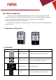
[键入文字] I Product introduction i31S voice access is a full digital network door phone, with its core part adopts mature VoIP solution (Broadcom chip), stable and reliable performance, hands-free adopting digital full-duplex mode, voice loud and clear, generous appearance, solid durable, easy for installation, comfortable keypad and low power consumption. i31S voice access supports entrance guard control, voice intercom, ID card and keypad remote to open the door. 1. Appearance of the product 2.
[键入文字] Lock Status Door unlocking: On Door locking: Off Call status Standby: Off Call Holding: Blink with 1s Calls: On Ring status Standby: Off Ringing: On Network/SIP Registration Network error: Blink with 1s Network running: Off Registration failed: Blink with 3s Registration succeeded: On II Start Using Before you start to use the equipment, please make the following installation. 1.
[键入文字] 【Note】When the device is in active mode, it can drive 12V/650mA switch output maximum, to which a standard electric-lock or another compatible electrical appliance can be connected. When using the active mode, it is 12V DC in output. When using the passive mode, output is short control (normally open mode or normally close mode). 3) Wiring instructions NO: Normally Open Contact. COM: Common Contact. NC: Normally Close Contact.
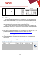
[键入文字] √ √ 2. Quick Setting The product provides a complete function and parameter setting. Users may need to have the network and SIP protocol knowledge to understand the meaning represented by all parameters. In order to let equipment users enjoy the high quality of voice service and low cost advantage brought by the device immediately, here we list some basic but compulsory setting options in this section to let users know how to operate without understanding such complex SIP protocols.
[键入文字] III Basic operation 1. Answer a call When a call comes in, the device will answer automatically. If you cancel auto answer feature and set auto answer time, you will hear the bell ring at the set time and the device will auto answer after a timeout. 2. Call Configure shortcut key as hot key and setup a number, then press shortcut key can call the configured number. 3. End call Enable Release key hang up to end call. 4.
[键入文字] high-frequency short chirp. When door has been opened, the device will play sirens sound to prompt. IV Page settings 1. Browser configuration When the device and your computer are successfully connected to the network, enter the IP address of the device on the browser as http://xxx.xxx.xxx.xxx/ and you can see the login interface of the web page management. Enter the user name and password and click the [logon] button to enter the settings screen. 2.
[键入文字] 3. Configuration via WEB (1) System a) Information Information Field Name Explanation System Information Display equipment model, hardware version, software version, uptime, Last uptime and MEMinfo. Network Shows the configuration information for WAN port, including connection mode of WAN port (Static, DHCP, PPPoE), MAC address, IP address of WAN port. SIP Accounts Shows the phone numbers and registration status for the 2 SIP LINES.
[键入文字] b) Account Through this page, user can add or remove users depends on their needs and can modify existing user permission.
[键入文字] c) Configurations Configurations Field Name Explanation Export Save the equipment configuration to a txt or xml file. Please note to Right click on Configurations the choice and then choose “Save Link As.” Import Configurations Browse to the config file, and press Update to load it to the equipment. Reset to factory defaults This will restore factory default and remove all configuration information.
[键入文字] e) Auto Provision Auto Provision Field Name Explanation Common Settings Current Configuration Version Show the current config file’s version. If the version of configuration downloaded is higher than this, the configuration will be upgraded. If the endpoints confirm the configuration by the Digest method, the configuration will not be upgraded unless it differs from the current configuration General Configuration Version Show the common config file’s version.
[键入文字] Save Auto Provision Information Save the auto provision username and password in the phone until the server url changes DHCP Option Option Value The equipment supports configuration from Option 43, Option 66, or a Custom DHCP option. It may also be disabled. Custom Option Value Custom option number. Must be from 128 to 254. SIP Plug and Play (PnP) Enable SIP PnP If this is enabled, the equipment will send SIP SUBSCRIBE messages to a multicast address when it boots up.
[键入文字] f)FDMS FDMS Settings Enable FDMS Enable/Disable FDMS configuration FDMS Interval The time to send sip Subscribe information to the FDMS server on a regular basis.
[键入文字] Syslog is a protocol used to record log messages using a client/server mechanism. The Syslog server receives the messages from clients, and classifies them based on priority and type. Then these messages will be written into a log by rules which the administrator has configured. There are 8 levels of debug information. Level 0: emergency; System is unusable. This is the highest debug info level. Level 1: alert; Action must be taken immediately.
[键入文字] (2) Network a) Basic Field Name Explanation Network Status IP The current IP address of the equipment Subnet mask The current Subnet Mask Default gateway The current Gateway IP address MAC The MAC address of the equipment MAC Timestamp Get the MAC address of time. Settings Select the appropriate network mode. The equipment supports three network modes: Static IP Network parameters must be entered manually and will not change. All parameters are provided by the ISP.
[键入文字] Secondary DNS Server Enter the server address of the Secondary DNS. After entering the new settings, click the APPLY button. The equipment will save the new settings and apply them. If a new IP address was entered for the equipment, it must be used to login to the phone after clicking the APPLY button. Service Port Settings Web Server Type Specify Web Server Type – HTTP or HTTPS HTTP Port Port for web browser access. Default value is 80. To enhance security, change this from the default.
[键入文字] 21 / 54
[键入文字] Field Name Explanation VPN IP Address Shows the current VPN IP address. VPN Mode Enable VPN Enable/Disable VPN. L2TP Select Layer 2 Tunneling Protocol OpenVPN Select OpenVPN Protocol. (Only one protocol may be activated. After the selection is made, the configuration should be saved and the phone be rebooted.) Layer 2 Tunneling Protocol (L2TP) L2TP Server Address Authentication Name Authentication Password Set VPN L2TP Server IP address. Set User Name access to VPN L2TP Server.
[键入文字] 23 / 54
[键入文字] SIP Field Name Explanation Basic Settings (Choose the SIP line to configured) Line Status Display the current line status at page loading. To get the up to date line status, user has to refresh the page manually. Username Enter the username of the service account. Display name Enter the display name to be sent in a call request.
[键入文字] Response Single Codec If setting enabled, the device will use single codec in response to an incoming call request Ring Type Set the ring tone type for the line Conference Type Set the type of call conference, Local=set up call conference by the device itself, maximum supports two remote parties, Server=set up call conference by dialing to a conference room on the server Server Conference Number Set the conference room number when conference type is set to be Server Transfer Timeout Set the
[键入文字] Enable Session Timer Set the line to enable call ending by session timer refreshment.
[键入文字] Basic Settings Field Name Explanation SIP Settings Local SIP Port Set the local SIP port used to send/receive SIP messages. Registration Failure Retry Interval Set the retry interval of SIP REGISTRATION when registration failed. Enable Strict UA Match Enable or disable Strict UA Match STUN Settings Server Address STUN Server IP address Server Port STUN Server Port – Default is 3478.
[键入文字] Binding Period STUN blinding period – STUN packets are sent at this interval to keep the NAT mapping active. SIP Waiting Time Waiting time for SIP. This will vary depending on the network. TLS Certification File Upload or delete the TLS certification file used for encrypted SIP transmission.
[键入文字] Destination Configure the destination address and, if configured as a point-to-point call, write the peer IP address directly. Can also be set to domain name, by the device DNS server to resolve the specific IP address. If it is not configured, the IP address is 0.0.0.0. This is an optional configuration item Port Configure the signaling port of the other party. This is an optional configuration item.
[键入文字] Features Field Name Explanation Common Settings Switch Mode Monostable: there is only one fixed action status for door unlocking. Bistable: there are two actions and statuses, door unlocking and door locking. Each action might be triggered and changed to the other status. After changed, the status would be kept. Initial Value is Monostable Switch-On Duration Door unlocking time for Monostable mode only. If the time is up, the door would be locked automatically. Initial Value is 5 seconds.
[键入文字] Enable Card Reader Enable or disable card reader for RFID cards. Card Reader Working Mode Set ID card stats: Normal: This is the work mode, after the slot card can to open the door. Card Issuing: This is the issuing mode, after the slot card can to add ID cards. Card Revoking: This is the revoking mode, after the slot card can to delete ID cards. Limit Talk Duration If enabled, calls would be forced ended after talking time is up.
[键入文字] Enable Auto Dial Out Enable Auto Dial Out Auto Dial Out Time Set Auto Dial Out Time Enable Auto Answer Enable Auto Answer function Auto Answer Timeout Set Auto Answer Timeout No Answer Auto Hangup Enable automatically hang up when no answer Auto Hangup Timeout Configuration in a set time, automatically hang up when no answer Dial Fixed Length to Send Enable or disable dial fixed length to send.
[键入文字] Audio Setting Field Name Explanation First Codec The first codec choice: G.711A/U, G.722, G.723.1, G.726-32, G.729AB Second Codec The second codec choice: G.711A/U, G.722, G.723.1, G.726-32, G.729AB, None Third Codec The third codec choice: G.711A/U, G.722, G.723.1, G.726-32, G.729AB, None Fourth Codec The forth codec choice: G.711A/U, G.722, G.723.1, G.726-32, G.729AB, None DTMF Payload Type The RTP Payload type that indicates DTMF.
[键入文字] c) Video This page allows you to set the video capture and video encode. Video Field Name Explanation Video Capture IRCUT Mode Auto: IRCUT switches according to the actual ambient light level of the camera Synchronization: The switching of the IRCUT is determined by the actual brightness of the IR lamp.
[键入文字] DNC Threshold In the Day / Night mode Auto option, the color switching black and white threshold is set Backlight Compensation In front of a very strong background light can see people or objects clearly AutoFill Sensitivity In the environment changes in light and shade, the higher the sensitivity the faster the video changes Fill Light Enable or disable Fill Light Video Encode Encode Format Only H.
[键入文字] d) MCAST It is easy and convenient to use multicast function to send notice to each member of the multicast via setting the multicast key on the device and sending multicast RTP stream to pre-configured multicast address. By configuring monitoring multicast address on the device, monitor and play the RTP stream which sent by the multicast address.
[键入文字] stream, and keep the current multicast session in state; If it is not enabled, the device will automatically ignore all receiving multicast RTP stream. Web Settings: The multicast SS priority is higher than that of EE, which is the highest priority. Note: when pressing the multicast key for multicast session, both multicast sender and receiver will beep. Listener configuration Blue part (name) "Group 1","Group 2" and "Group 3" are your setting monitoring multicast name.
[键入文字] The purpose of setting monitoring multicast "Group 1" or "Group 2" or "Group 3" launched a multicast call. All equipment has one or more common non multicast communication. When you set the Priority for the disable, multicast any level will not answer, multicast call is rejected.
[键入文字] e) Action URL Action URL Event Settings URL for various actions performed by the phone. These actions are recorded and sent as xml files to the server. Sample format is http://InternalServer /FileName.
[键入文字] Time/Date Field Name Explanation Network Time Server Settings Time Synchronized via Enable time-sync through SNTP protocol SNTP Time Synchronized via DHCP Enable time-sync through DHCP protocol Primary Time Server Set primary time server address Secondary Time Server Set secondary time server address, when primary server is not reachable, the device will try Time zone Select the time zone Resync Period Time of re-synchronization with time server to connect to secondary time server to get
[键入文字] Hour End The DST end hour Manual Time Settings The time set by hand, need to disable SNTP service first.
[键入文字] Click the to choose to import remote access list file (access List.csv) and then clicking can batch import remote access rule. Access Table According to entrance guard access rules have been added, you can choose single or multiple rules on this list to delete operation. Add Access Rule Name(necessary) User name Location Virtual extension number, used to make position call instead of real number. It might be taken with unit number, or room number. ID RFID card number.
[键入文字] Type: Issuer and revocation When entrance guard is in normal state, swipe card (issuing card) would make entrance guard into the issuing state, and then you can swipe a new card, which the card would be added into the database; when you swipe the issuing card again after cards added done, entrance guard would return to normal state. Delete card operation is the same with issuing card. The device can support up to 10 admin cards, 1000 copies of ordinary cards.
[键入文字] 2. If the opening door way is remote access, it wound display the remote extension’s number. 3. If the opening door way is local access, there is no display information. Open type: 1. Local, 2. Remote, 3. Brush card (Temporary Card, Valid Card and Illegal Card). Note: there are three kinds of brushing card feedback results. 1. Temporary Card (only added ) the card number, without adding other rules ) Type 2. Valid Card (added access rules) 3.
[键入文字] Hot Key You might enter the phone number in the input box. When you press the shortcut key, equipment would dial preset telephone number. This button can also be used to set the IP address: you can press the shortcut key to directly make a IP call.
[键入文字] operation mechanism You can define the DSS Key configuration with multicast address, port and used codec. The device can configure via WEB to monitor the multicast address and port. When the device make a multicast, all devices monitoring the address can receive the multicast data. calling configuration If the device is in calls, or it is three-way conference, or initiated multicast communication, the device would not be able to launch a new multicast call.
[键入文字] Trigger Mode Alert message send to server When choosing the low level trigger (closed trigger), detect the input port 1 (low level) closed trigger. When choosing the high level trigger (disconnected trigger), detect the input port 1 (high level) disconnected trigger.
[键入文字] Alarm command When detected someone tampering the equipment, will be sent alarm to the corresponding server Reset command When the equipment receives the command of reset from server, the equipment will stop alarm Reset Alerting Status Directly stop the alarm from equipment in the Webpage Ring Type Set the Ring Type 48 / 54
[键入文字] V Appendix 1. Technical parameters Communication protocol SIP 2.0(RFC-3261) Main chipset Broadcom Keys Audio Speech flow DSS Key 1 (Stainless steel) Numeric keyboard Support MIC 1 Speaker 3W/4Ω Volume control Adjustable Full duplex speakerphone Support (AEC) Protocols RTP Decoding G.729、G.723、G.711、G.722、G.
[键入文字] 2. Basic functions 2 SIP lines PoE Enabled Full-duplex speakerphone (HF) Numeric keypad (Dial pad or Password input) Intelligent DSS Keys (Speed Dial/intercom etc) Wall-mounting / Flush-mounting Integrated RFID Card reader 1 indoor switch interface 1 electric lock relay Anti-tamper switch External power supply Door phone: call, password, RFID card, indoor switch Protection level: IP65, IK10, CE/FCC 3.
[键入文字] VI Other instructions 1. Open door modes Local 1) Local Password Set (the default is "6789") via DOOR PHONE\DOOR PHONE as above. 2) Use the device's keypad to input password and "#" key, then the door will be unlocked. Private access code Set and enable local authentication. Use the device's keypad to input access code and "#" key, then the door will be unlocked.
[键入文字] 1) Add Input a card’s ID, selected in the types and Clicked , you can add Issuer admin card. 2) Add Input a card’s ID, selected in the types and Clicked , you can add Revocation admin card. 3) Administrator Table Delete Administrator Select the admin card of need to delete, click . Add user cards Method 1: used to add cards for starters typically 1) In web page < EGS Setting\Card Reader Working Mode> option, s
[键入文字] 5) Click , Card Reader would be back to the Normal status. 6) The issuing records can be found from the Access table list. Method 2: used to add cards for professionals 1) Use to touch card reader induction area, and it would be entered issuing card status. 2) Use new card to touch card reader induction area, and you might hear the confirmed indication tone from the device. Repeat step 2 to add more cards.
[键入文字] Delete user cards Method 1: used to batch delete cards for starters. 1) In web page option, select . 2) Click , Card Reader would be entered the revoking status. 3) Use card to touch card reader induction area, and you might hear the card reader confirmed indication tone. Repeat step 3 to delete more cards. 4) In web page option, select .