T-910CM 9 Universal Ceiling Mount Monitor M E EXIT AV MENU ON POWER OFF OWNER S MANUAL
SPECIFICATIONS Power Requirements DC 12V Power Consumption 9W Screen Size 9 T F T- L C D Screen Format 16:9 Resolution Pixel 1920x234 A/V Inputs 2 A/V RCA Inputs Dimensions(With shroud) 11 . 3 ( L ) X 9 . 6 ( W ) X 2 . 4 ( H ) i n c h e s Dimensions(Without shroud) IR Power Requirements 10.8(L)X9.4(W)X2.1(H)inches DC 12V IR Power Consumption 3W IR Transmitter Frequency Right 2.8MHz LCD Panel Type Active Matrix TFT Compatible video standard N T S C / PA L A u t o S e l e c t Left 2.
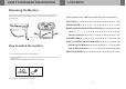
HOW TO OPERATE THE MONITOR CONTENTS Releasing the Monitor Push the open button (located on the front edge of the screen housing) a n d l o w e r t h e m o n i t o r t o t h e d e s i r e d a n g l e . Yo u c a n a l s o a d j u s t t h e swivel angle. CAUTION 4 INSTALLATION 5 NAME AND FUNCTION OF EACH PARTS 6 M E EXIT , Please read this User s Manual in detail and use the set properly. AV MENU ON POWER OFF Make this arrow in DOWN direction only.
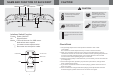
CAUTION CONNECTIONS , Please read and observe all warnings and instructions in this owner s manual and those marked on the unit. Retain this booklet for future reference. There are two kinds of alarm symbols as follows: The lightening flash with arrowhead symbol within an equilateral triangle is intended to alert the user to the, presence of dangerous voltage within the product s enclosure that may be of sufficient magnitude to constitute a risk of electric shock to WARNING people.
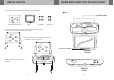
NAME AND FUNCTION OF EACH PART MENU Button OSD MENU EXIT Button Dome Light Button CAUTION POWER Button CAUTION M E EXIT AV MENU POW ER ON Watching the monitor for an extended period of time with the engine turned off may deplete the vehicle s battery. Quality installations are best performed by qualified and certifled installers. OFF This product is designed for operation with a 12 Volt DC, negative ground vehicle. It is not suitable for operation under other conditions or voltages.
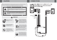
INSTALLATION NAME AND FUNCTION OF EACH PART 1. Open the package and check that these items are presents. Unit Dome light UNIT INSTALLATION PLATE SCREW A SCREW B M E EXIT AV MENU POWER OFF ON 2. Connect the external compoments to the RCA cable or AV output. (Refer to the connection diagram on page 8) 3. Match the position of installation bracket and installation plate with screw A. Infrared Transmitter Monitor (Front) M PLAY AV MENU ON POWER OFF Audio Reset 4.