Persona C16 Card Printer Service Manual (Rev. 5.
RESTRICTED USE ONLY FARGO Electronic, Inc. Persona C16 Card Printer Service Manual (Rev. 5.0), property of FARGO Electronics, Incorporated Copyright 2002, 2003, 2004, 2005, 2006 by FARGO Electronics, Incorporated. All rights reserved. Printed in the United States of America.
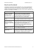
RESTRICTED USE ONLY FARGO Electronic, Inc. How to use the manual The Persona C16 Card Printer Service Manual (Rev. 5.0) is, in fact, the troubleshooting and field service manual for the entire Card Printer. The manual is designed to provide Installers and Technicians with quick, efficient lookup of related procedures, components and terms. The manual can be used effectively either in soft or hard copy, depending on the preference of the Installer or Technician.
RESTRICTED USE ONLY FARGO Electronic, Inc. Safety Messages (review carefully) Symbol Critical Instructions for Safety purposes Danger: Failure to follow these installation guidelines can result in death or serious injury. Information that raises potential safety issues is indicated by a warning symbol (as shown to the below). Caution: • To prevent personal injury, refer to the following safety messages before performing an operation preceded by this symbol.
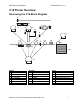
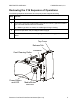
RESTRICTED USE ONLY FARGO Electronic, Inc. C16 Printer Overview Reviewing the C16 Block Diagram 9 15 7 4 3 11 10 8 6 14 17 14 5 1 14 13 12 14 16 2 Motors 1 Card Feed 2 Print Stepper 3 Ribbon Drive 4 Print Headlift Persona Sensors 5 Card Feed 6 Ribbon Sensor 7 Ribbon Encoder 8 Headlift 9 Cover Interlock 10 Printhead Thermistor 11 Ribbon ID C16 Card Printer Service Manual (Rev. 5.
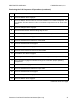
RESTRICTED USE ONLY FARGO Electronic, Inc. Reviewing the C16 Sequence of Operations The following sequence describes a full color print job with magnetic encoding. Process Step 1 The File information is received from the PC 2 The Printer checks the installed Ribbon type stored in memory against the Ribbon type command that was sent from the Printer. a. If Ribbon type does not match, the media light will begin flashing. 3 The Card input Motor and print Stepper Motor engage.
RESTRICTED USE ONLY FARGO Electronic, Inc. Reviewing the C16 Sequence of Operations (continued) Step Process 5 The Print Ribbon Drive engages. 6 The Print Ribbon Sensor looks for the color transition from Yellow to Magenta. The Print Ribbon Encoder detects number of revolutions required to use an entire color panel. 7 The Print Stepper Motor engages. 8 The Card Feed Sensor detects trailing edge of card. 9 The Print Stepper Motor queues card to the middle of the platen roller.
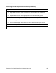
RESTRICTED USE ONLY FARGO Electronic, Inc. Reviewing the C16 Sequence of Operations (continued) Step Process 23 After Ribbon advances a few encoder clicks, assume Ribbon free of card. All Stop. 24 Repeat steps 9 through 23 for appropriate number of color/overlay panels. 25 The Card Feed Stepper Motor engages to queue card for magnetic encoding. 26 The Encoding data is written to the card. 27 The Card feed Stepper will requeue the card for each verification pass required.
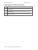
RESTRICTED USE ONLY FARGO Electronic, Inc. Reviewing the C16 Boot up Sequence Step Process 1 On Power up, the Printer checks the current state of the Card Feed Sensor and the Headlift Sensor. 2 If the Headlift Sensor is found to be open, the Headlift Motor will turn until a closed state is seen. 3 If the Card Feed Sensor is found to be blocked, the Card Feed Stepper will engage to eject the card. Persona C16 Card Printer Service Manual (Rev. 5.
RESTRICTED USE ONLY Fargo Electronics, Inc.
RESTRICTED USE ONLY Fargo Electronics, Inc.
RESTRICTED USE ONLY Fargo Electronics, Inc.
RESTRICTED USE ONLY Fargo Electronics, Inc.
RESTRICTED USE ONLY Fargo Electronics, Inc.
RESTRICTED USE ONLY Fargo Electronics, Inc. Section 1: Specifications The purpose of this section is to provide the User with specific information on the Regulatory Compliances, Agency Listings, Technical Specifications and Functional Specifications for this Printer. Regulatory Compliances Term Description CSA The Printer manufacturer has been authorized by UL to represent the Card Printer as CSA Certified under CSA Standard 22.2.
RESTRICTED USE ONLY Fargo Electronics, Inc. Agency Listings Term Description Emissions Standards CE, FCC, CRC c1374, BSMI, ITS (EN 55022 Class B:1995, FCC Class B, EN 82082-1:1997). Safety Standards UL 1950, CSA C2.2 No.950-95 and TüV-GS (EN 60950 A1-A4, A11). Persona C16 Card Printer Service Manual (Rev. 5.
RESTRICTED USE ONLY Fargo Electronics, Inc. Technical Specifications Type Description Print Method Dye-Sublimation/Resin Thermal Transfer Resolution 300 dpi (11.8 dots/mm) Colors Up to 16.7 million Print Speed 30 seconds per card/120 cards per hour (YMCKO) (Note: (): Indicates the print ribbon type and the number of ribbon panels printed where Y=Yellow, M=Magenta, C=Cyan, K=Resin Black, B=DyeSublimation Black and O=Overlay.
RESTRICTED USE ONLY Fargo Electronics, Inc. Technical Specifications (continued) Type Description Card Input Hopper Capacity 100 cards (30 mil) Memory 2MB RAM Printer Drivers Windows 95, Windows 98, Windows Millennium, Windows NT 4.0, Windows 2000, Windows XP System Requirements IBM-PC or compatible, Windows 95/98, Windows NT 4.
RESTRICTED USE ONLY Fargo Electronics, Inc. Visual Security Solutions (Specifications) VeriMarkTM Cards - 2-D holographic foil application VeriMarkTM Cards are a low cost, customized 2-D holographic foil application, that is made in two steps. • The first step is to emboss a base foil 1.9 cm (L) x 1.3 cm (H) onto the surface of a blank white card. • The second step is debossing a custom made dye into the surface of the base foil leaving a customized image, logo or text provided by the customer.
RESTRICTED USE ONLY Fargo Electronics, Inc. Visual Security Card Stock - Tolerances • Tolerance of base foil placement will equal +/- .010" from the nearest edges of the card • Tolerance of layered foil will equal +/- .010" VeriMarkTM - Application Specifications VeriMarkTM foils will cover a dimensional area of 1.9 cm length x 1.3 cm height.
RESTRICTED USE ONLY Fargo Electronics, Inc. Functional Specifications This Card Printer utilizes two different, yet closely related printing technologies to achieve its remarkable direct-to-card print quality for dye-sublimation and resin thermal transfer. The Card Printer will print from any IBM-PC® or compatible running Windows® 95/98/Me, Windows NT 4.0, Windows 2000 or Windows XP.
RESTRICTED USE ONLY Fargo Electronics, Inc. Printer Components: Top Cover to Parallel Interface Card Components Description Top Cover This cover opens to allow access to the Printhead, print ribbon and card path. (Note: This cover must be closed in order for the Printer to begin printing.) Release tab This tab unlatches the Top Cover. Printhead This Printer component actually does the printing.
RESTRICTED USE ONLY Fargo Electronics, Inc. Printer Components: Centronics-Type Parallel Interface The Card Printer is equipped with a standard 8-bit centronics-type parallel interface port. This communication port is the means through which the Printer receives data from the computer. This section describes the pin assignments and signal specifications for this port.
RESTRICTED USE ONLY Fargo Electronics, Inc. Printer Components: Resin-Only Print Ribbons Resin-only print ribbons consist of a continuous roll of a single resin color. No protective overlay panel (O) is provided since resin images do not require the protection of such an overlay.
RESTRICTED USE ONLY Fargo Electronics, Inc. Printer Components: Dye-Sublimation Print Ribbons The Printer requires both specialized and authorized print ribbons in order to print and function properly. Step 1 Procedure Do not run the cards with a contaminated, dull or uneven surface through the Printer. Caution: Printing onto such cards will ultimately lead to poor print quality and will greatly reduce the life of the Printhead.
RESTRICTED USE ONLY Fargo Electronics, Inc. Printer Components: Dye-Sublimation Print Ribbons (continued) Type Description DyeSublimationOnly Print Ribbon It is available in a monochrome version. DyeSublimation Black (BO) (provides 500 prints) • This ribbon consists of dye-sublimation ribbon panels, which alternate with a clear protective overlay (O) panel. • Dye-Sublimation images must have an overlay panel applied to them (or they will quickly begin to wear or fade).
RESTRICTED USE ONLY Fargo Electronics, Inc. Printer Components: Blank Cards Type Description Card Size The Card Printer accepts standard CR-80 sized cards (3.370” L x 2.125” W/85.6mm L x 54mmW) and CR-79 Adhesive Back (3.303” L x 2.2125” W/83.9mm L x 52.1mmW) with a thickness of 20 to 30 mil. Card Design The Printer will print onto any card with a clean, level and polished PVC surface.
RESTRICTED USE ONLY Fargo Electronics, Inc. Reviewing the upgraded 81754 PVC Cards The upgraded 81754 PVC cards are designed for a sharper card image quality and for reduced debris and defects on Fargo Card Printers. Carefully read these detailed notes and instructions before applying this information to your Fargo printer or printers. • Technician Note 1: The new card lot number starts at Lot # 2010104 with date codes that started on 04/01/2003.
RESTRICTED USE ONLY Fargo Electronics, Inc. Reviewing the upgraded 81754 PVC Cards (continued) Follow these two (2) instructions below: 1. Instruction for new 81754 PVC card stock: Increase the Printer Driver’s Dye-Sub Intensity to print with the new 81754 PVC card stock on Fargo Card Printers (S/N A319 and older). See the chart provided below. See the appropriate Fargo service documents for specific Printer Driver instructions.
RESTRICTED USE ONLY Fargo Electronics, Inc. Section 2: General Troubleshooting This section provides Troubleshooting procedures for this Printer for Communication Errors, Card Feed Errors, Card Jam Errors, Encoding Errors and Diagnosing Image Problems. Safety Messages (review carefully) Symbol Critical Instructions for Safety purposes Danger: Failure to follow these installation guidelines can result in death or serious injury.
RESTRICTED USE ONLY Fargo Electronics, Inc. Reviewing the TOP Line LCD Error/Status Messages Message Cause Solution Card Jam A card is jammed in the Printer. See the Resolving a Card Jam Error procedure in Section 2, page 34. Card Out/Not Fed Either the Card Hopper is out of cards or the Printer is unable to feed a card in from the Card Hopper. See the Resolving the Card Feeding Errors procedure in Section 2, page 28. Clearing Jam Indicates error or jam is being cleared. No action required.
RESTRICTED USE ONLY Fargo Electronics, Inc. Reviewing the TOP Line LCD Error/Status Messages (continued) Message Cause Solution Mag Verify Error The mag stripe was not encoded properly. See the Resolving the Mag Verify Error Message procedure in Section 2, page 46. Mag Verifying Indicates data on mag stripe is being verified. No action required. Print Cover Open The Top Cover is not properly shut. See the Resolving the Cover Open Error Message in Section 2, page 31.
RESTRICTED USE ONLY Fargo Electronics, Inc. BOTH Line LCD Error/Status Messages Message Cause Appears when the Resume button is pressed any time RESUME=Continue while the Printer is powered ON. CANCEL=Abort Also appears when the Cancel button is pressed during a print job. CANCEL=Abort RESUME=Reprint Appears when the Cancel button is pressed after an error has occurred. Solution Press the Resume button to return the Printer to its Ready mode or, if printing, to continue operation.
RESTRICTED USE ONLY Fargo Electronics, Inc. Communications Errors Resolving the Communication Errors Symptom(s): Incorrect output, communications error on PC or Printer, stalling, no response from Printer, no job printed, “paper out” error. Step 1 2 Procedure Confirm that the system meets the minimum requirements, as shown here: • IBM-PC or compatible.
RESTRICTED USE ONLY Fargo Electronics, Inc. Resolving the Communication Errors (continued) Step 3 Procedure Verify the use of an adequate data cable. a. Use a double-shielded parallel cable (no longer than six feet in length). (Note: Data transmission failure can be attributed to a long or faulty parallel cable.) b. Use a double-shielded, I-EEE 1284 compliant cable to reduce the effect of radio emissions from computers, monitors and other equipment that may broadcast Radio frequency interference (RFI).
RESTRICTED USE ONLY Fargo Electronics, Inc. Resolving the Communication Errors (continued) Step 6 Procedure Determine if the Parallel Port mode is set correctly or incorrectly a. Ensure that the parallel port is set to the Enhanced Communication Port (ECP) mode. (Note: The port mode can be determined by checking the Device Manager tab in the system control panel.) b. Change the computer’s BIOS if the port mode is not set to ECP.
RESTRICTED USE ONLY Fargo Electronics, Inc. Card Feeding Errors Resolving the Card Feeding Errors Symptom: Two or more cards feed at the same time or the cards will not feed at all. Step Procedure Clean the Input Roller. Caution: Turn off the Printer and unplug the power cord from the Printer. a. Remove all cards from the Printer's Card Input Hopper. b. Get a Cleaning Card from the Printer Cleaning Kit and remove its adhesive backing paper. c.
RESTRICTED USE ONLY Fargo Electronics, Inc. Using the Idler Spring Upgrade Kit The purpose of Technical Update No. 45 was to announce the release of the Idler Spring Upgrade Kit for the Persona C11, M11 and C16 Card Printers. • Improvement: The new Idler Spring Upgrade Kit provides more reliability when feeding cards through the Card Printer. (Technician Note: The previous Idler Springs were prone to breaking at an approximate output of 1000 cards.) • Order No.
RESTRICTED USE ONLY Fargo Electronics, Inc. Print Process Errors Resolving a Headlift Error Symptom: The Printhead continuously cycles or does not cycle at all. Step 1 Procedure Cycle the Headlift Motor. a. Press both buttons on the front control panel. b. Verify that the Headlift Motor turns. • 2 If the Motor does not turn, continue to Step 2. Test the Headlift Motor. a. Unplug the Printer. b. Remove the back cover. c. Disconnect the Headlift Motor from the Main Board. d.
RESTRICTED USE ONLY Fargo Electronics, Inc. Resolving the Cover Open Error Message Symptom: The Printer errors immediately after sending a print job or the rollers do not operate by pressing the cottons on the front panel (when the cover is open). Step 1 Procedure Reseat the Cover Switch. a. Open the top cover and remove the Print Ribbon. b. Remove the two screws from the Cover Switch located near the ribbon take up hub. c. Reseat the switch on the Printer side plate and carefully replace the screws. d.
RESTRICTED USE ONLY Fargo Electronics, Inc. Resolving the Blank Output issues Symptom: A card is ejected blank (that should be printed). Step 1 Procedure Run a Self-Test. a. Clear any Card jams. b. Unplug the power from the Printer. c. While holding down the Pause/Resume button, reapply power. (Note: A self-test card will be printed.) 2 Look for an image on the Ribbon. a. Open the top cover after a Self-Test has been run. b. Remove the Print Ribbon from the Printer. c.
RESTRICTED USE ONLY Fargo Electronics, Inc. Resolving the Blank Output issues (continued) Step 4 Procedure Check the Printhead connections. a. Open the top print cover. b. Remove the two (2) thumbscrews from the Printhead cover plate and remove the cover plate. c. Check to ensure that Power and Data Cables (that connect to the printhead) are properly seated. d. Remove the Back Cover. 5 • Ensure that the Printhead Power Cable is properly seated on J11 on the Power board.
RESTRICTED USE ONLY Fargo Electronics, Inc. Card Jam Errors Resolving a Card Jam Error Symptoms: The card is physically jammed in the Printer or a Card Sensor is reporting a card is present. Step 1 Procedure Look for a jammed card in the Printer. a. Open the Printer’s top cover. b. Remove the ribbon from the Printer. c. Check to see if a card is jammed in the print station of the Printer. 2 • If a card is found in the print station, continue to Step 2.
RESTRICTED USE ONLY Fargo Electronics, Inc. Ribbon Errors Resolving the Skipping Ribbon Panel issues Symptom: The Printer is using more than one set of ribbon panels to print one side of a card. Step 1 Procedure Calibrate the Ribbon Sensor. (See the next page.) a. Reset the Printer to clear any Error Messages by removing Power and reapplying. b. Open the Printer Control Panel from the Computer. • If using Windows 95/98/ME, right click on the C11_C16 Card Printer Icon and select Properties.
RESTRICTED USE ONLY Fargo Electronics, Inc. Resolving the Skipping Ribbon Panel issues (continued) See the previous procedure in this section. Continued on the next page Persona C16 Card Printer Service Manual (Rev. 5.
RESTRICTED USE ONLY Fargo Electronics, Inc. Resolving the Skipping Ribbon Panel issues (continued) Step 2 Procedure Test the Encoder Sensor. a. Remove the back cover. b. Using a Digital Voltmeter, connect the negative lead to ground. c. Connect the positive lead to Pin 4 of J13. d. Persona • If blocked, the voltage should read 4.9 to 5.5 volts DC. • If unblocked, the Sensor should read 0.15 to 0.18 volts DC. If the voltages are not correct, replace the Sensor.
RESTRICTED USE ONLY Fargo Electronics, Inc. Resolving the Wrong Ribbon error (being displayed incorrectly) Symptom: A Wrong Ribbon Error is shown on the LCD even though the correct ribbon is installed in the Printer. Step 1 Procedure Verify the driver settings are correct. a. Open the Printer Control Panel from the Computer. • If using Windows 95/98/ME, right click on the C11_C16 Card Printer Icon and select Properties. • If using Windows NT 4.
RESTRICTED USE ONLY Fargo Electronics, Inc. Resolving the Wrong Ribbon error (being displayed incorrectly) (continued) Step 2 Procedure Test the Ribbon ID Sensor. a. Unplug the Printer. b. Remove the back cover. c. Flip switches 1,2,3 and 4 on the bank of DIP switches in the Main Board corner. d. With the top covers closed, apply power to the Printer while holding down the Pause/Resume button. e. Open up the Top Print Cover. f. Slowly rotate the supply side of the ribbon.
RESTRICTED USE ONLY Fargo Electronics, Inc. Resolving the Ribbon Error/Out Error Message Symptom: A Ribbon Error/Out message is displayed on the LCD Step 1 Procedure Calibrate the Ribbon Sensor. a. Reset the Printer to clear any Error Messages by removing Power and reapplying. b. From the Computer, open the Printer control panel. • If using Windows 95/98/ME, right click on the C11_C16 Card Printer Icon and select Properties. • If using Windows NT 4.
RESTRICTED USE ONLY Fargo Electronics, Inc. Resolving the Ribbon Breaking issues Symptom: The Ribbon breaks when printing. Step 1 Procedure Calibrate the Ribbon Sensor. a. Reset the Printer to clear any Error Messages by removing Power and reapplying. b. From the Computer, open the Printer control panel. • If using Windows 95/98/ME, right click on the C11_C16 Card Printer Icon and select Properties. • If using Windows NT 4.0, right click on the C11_C16 Card Printer and select Document Defaults.
RESTRICTED USE ONLY Fargo Electronics, Inc. Resolving the Ribbon Breaking issues (continued) See the previous procedure in this section. Persona C16 Card Printer Service Manual (Rev. 5.
RESTRICTED USE ONLY Fargo Electronics, Inc. Resolving the Ribbon Breaking issues (continued) Step 2 Procedure Determine where the ribbon is breaking. a. Open the Top Print Cover. b. Remove the ribbon from the Printer. c. Inspect the ribbon at the break point. 3 • If the Ribbon broke before any print was applied to the card, continue to Step 3. • If the Ribbon broke after applying the print to the card, continue to Step 4. Adjust the Image Placement. a.
RESTRICTED USE ONLY Fargo Electronics, Inc. Resolving the Ribbon Breaking issues (continued) See the previous procedure in this section. Continued on the next page Persona C16 Card Printer Service Manual (Rev. 5.
RESTRICTED USE ONLY Fargo Electronics, Inc. Resolving the Ribbon Breaking issues (continued) Step 4 Procedure Adjust the Image Placement positively. a. Reset the Printer to clear any Error Messages by removing Power and reapplying. b. Open the Printer Control Panel from the Computer. • If using Windows 95/98/ME, right click on the C11_C16 Card Printer Icon and select Properties. • If using Windows NT 4.0, right click on the C11_C16 Card Printer and select Document Defaults.
RESTRICTED USE ONLY Fargo Electronics, Inc. Encoding Errors Resolving the Mag Verify Error Message Symptoms: A Mag Verify error is displayed on the LED when attempting to encode. Step Procedure 1 Check to ensure that the cards are loaded with the Magnetic Stripe facing down and towards the back of the Printer. 2 Verify the Driver settings if cards are loaded properly. See the Using the Magnetic Encoding tab procedure in Section 3, page 88. See the Magnetic Encoding tab window on next page.
RESTRICTED USE ONLY Fargo Electronics, Inc. Resolving the Mag Verify Error Message (continued) See the previous procedure in this section. Persona C16 Card Printer Service Manual (Rev. 5.
RESTRICTED USE ONLY Fargo Electronics, Inc. Resolving the Printer’s inability to read Encoded Data Step Procedure 1 Verify that the cards are loaded properly with the Magnetic Stripe facing down and towards the back of the Printer. 2 Verify that the card is encoded with magnetic data by using a Magnetic Imager or Developer Solution. 3 Use WordPad (a Windows 95/ 98/ ME/ NT/ 2000/XP word processing program in the Accessories Program Group). a. Go to the File menu and select Page Setup. b.
RESTRICTED USE ONLY Fargo Electronics, Inc. Resolving Data intended for Magnetic Stripe (being printed on the card) problem Step Procedure 1 Confirm that the application is formatting the magnetic string correctly. See the Using the Magnetic Track Options procedure in Section 3, page 104. 2 Use WordPad (a Windows 95/ 98/ ME/ NT/ 2000/XP word processing program in the Accessories Program Group). a. Go to the File menu and select Page Setup. b.
RESTRICTED USE ONLY Fargo Electronics, Inc. Diagnosing Image Problems Resolving the Pixel Failure problems Symptom: A thin line or scratch travels the entire length of the card. Step Procedure 1 Check the card stock for scratches. Replace the cards (as needed). 2 Examine the Printhead for visible damage. 3 Clean the Printhead. See Cleaning the Printhead procedure in Section 4, page 150. 4 Clean the Platen Rollers. See Cleaning the Platen Rollers procedure in Section 4, page 153.
RESTRICTED USE ONLY Fargo Electronics, Inc. Resolving the Card Surface Debris problems Symptom: Prints have spots (white or colored voids) and/or dust on them. Step Procedure 1 Be sure the cards are clean and stored in a dust-free environment. Do not use cards with embedded contaminants in the surface. 2 Clean the inside of the Printer. See Cleaning the Printer’s Interior procedure in Section 4, page 154. 3 Clean the Platen Rollers. See Cleaning the Platen Rollers procedure in Section 4, page 153.
RESTRICTED USE ONLY Fargo Electronics, Inc. Resolving the Incorrect Image Darkness problems Symptom: Printed cards are too dark or too light. Step Procedure 1 Run a self-test to ensure that the issue is not with the driver settings. 2 Adjust the Dye-Sub Intensity setting within the Image Color tab of the Printer Driver. See Using the Image Color tab procedure in Section 3, page 95. Continued on the next page Persona C16 Card Printer Service Manual (Rev. 5.
RESTRICTED USE ONLY Fargo Electronics, Inc. Resolving the Incorrect Image Darkness problems (continued) Step 3 Persona Procedure Correct the Image Darkness. See Using the Image Darkness option in Section 3, page 79. C16 Card Printer Service Manual (Rev. 5.
RESTRICTED USE ONLY Fargo Electronics, Inc. Resolving the Ribbon Wrinkle problems Symptom: Printed cards have off-colored lines or streaks on them. Step Procedure 1 Confirm that the Printer is using the most current driver via: http://www.fargo.com 2 Reduce the Dye-Sub Intensity setting within the Image Color tab of the Printer Driver. See the Using the Image Color tab procedure in Section 3, page 95. Continued on the next page Persona C16 Card Printer Service Manual (Rev. 5.
RESTRICTED USE ONLY Fargo Electronics, Inc. Resolving the Ribbon Wrinkle problems (continued) Step 3 Persona Procedure Reduce the Image Darkness. See Using the Image Darkness option in Section 3, page 79. C16 Card Printer Service Manual (Rev. 5.
RESTRICTED USE ONLY Fargo Electronics, Inc. Resolving the Excessive Resin Printing problems Symptom: Black resin text and barcodes appear smeared or too thick. Step 1 Procedure Reduce the Resin Heat setting within the Image Color tab of the Printer Driver. See the Using the Image Color tab procedure in Section 3, page 95. Continued on the next page Persona C16 Card Printer Service Manual (Rev. 5.
RESTRICTED USE ONLY Fargo Electronics, Inc. Resolving the Excessive Resin Printing problems (continued) Step 2 Persona Procedure Reduce the Image Darkness. See Using the Image Darkness option in Section 3, page 79. C16 Card Printer Service Manual (Rev. 5.
RESTRICTED USE ONLY Fargo Electronics, Inc. Resolving the Incomplete Resin Printing problems Symptom: Black resin text and barcodes appear faded or too light. Step Procedure 1 Increase the Resin Heat setting within the Image Color tab of the Printer Driver. See the Using the Image Color tab procedure in Section 3, page 95. 2 Increase the Image Darkness. See Using the Image Darkness option in Section 3, page 79. Persona C16 Card Printer Service Manual (Rev. 5.
RESTRICTED USE ONLY Fargo Electronics, Inc. Resolving the Image Placement problems Symptom: Printing is cut off or is not centered on the card or a white border appears. Step 1 Procedure Verify if the Image Position option within the Calibrate tab is set incorrectly. a. Open the Printer Control Panel from the Computer. • If using Windows 95/98/ME, right click on the C11_C16 Card Printer Icon and select Properties. • If using Windows NT 4.
RESTRICTED USE ONLY Fargo Electronics, Inc. Resolving the Image Placement problems (continued) Step 2 Procedure Verify if the Image Placement setting is set correctly or incorrectly. See Graphic A on the next page. a. Open the Printer Control Panel from the Computer. • If using Windows 95/98/ME, right click on the C11_C16 Card Printer Icon and select Properties. • If using Windows NT 4.0 right click on the C11_C16 Card Printer and select Document Defaults.
RESTRICTED USE ONLY Fargo Electronics, Inc. Resolving the Image Placement problems (continued) This is Graphic A. This is Graphic B. Persona C16 Card Printer Service Manual (Rev. 5.
RESTRICTED USE ONLY Fargo Electronics, Inc. Resolving the Poor Image Quality problems Symptom: Photos on the cards look pixilated or grainy, as shown below.
RESTRICTED USE ONLY Fargo Electronics, Inc. Running the Self Test Perform a self-test after (a) an initial setup of the Printer, (b) a calibration procedure has been conducted or (c) a part has been replaced to check for proper Printer operation. Step 1 Procedure Verify that a full-color ribbon is installed and that cards are properly loaded. Caution: If the power is ON, disconnect the Power Cable from the Printer’s rear panel. 2 Press and hold the Pause/Resume button.
RESTRICTED USE ONLY Fargo Electronics, Inc. Using the DIP Switch (Self-test) Step 1 Procedure Activate any of these diagnostic tests and Calibration modes. See Running the Self Test in Section 2, page 63. During the activation of the Self-test, the Printer will: • Detect the change to the DIP Switch Settings. See Using the DIP Switch Self Test in Section 2, page 64. • Operate the Printer in that selected Test or Calibration mode.
RESTRICTED USE ONLY Fargo Electronics, Inc. Setting the DIP Switch Settings The capital letter “X” indicates that the switch should be set to ON or DOWN. SW1 SW2 SW3 SW4 X X X X Test5x3 is a standard YMCKO test card. X X Mag123A is a mag-only test card (records on the Magnetic Stripe). X X X Persona Diagnostic modes The RibTest calibrates the Ribbon Color Sensor (none or anything except Mono Resin). X X The ResinTest is a premium resin test card.
RESTRICTED USE ONLY Fargo Electronics, Inc. Running the 15-Shade Self Test This is the Self-test that appears when specific changes are made to the DIP Switch Settings. Persona C16 Card Printer Service Manual (Rev. 5.
RESTRICTED USE ONLY Fargo Electronics, Inc. Interfacing Information The Printer is equipped with a standard 8-bit Centronics-type Parallel Data Communications Port. (Note: The Printer's Parallel Interface Connector is a standard 36-pin Amp type with two metal-wire retaining clips. It mates with a standard PC to Printer parallel cable.) Caution: For best results, keep the Interface Cable to less than six (6) feet.
RESTRICTED USE ONLY Fargo Electronics, Inc.
RESTRICTED USE ONLY Fargo Electronics, Inc.
RESTRICTED USE ONLY Fargo Electronics, Inc. Reviewing the Centronics Parallel Pin Assignments (continued) Signal Funtion Bit Name DB-25 M 1284A Pin # Centronics M 1284B Pin # Ch. Grnd 17 Perif. Hi. 18 Unused 15 Unused 33 Unused 34 Unused 35 Persona C16 Card Printer Service Manual (Rev. 5.
RESTRICTED USE ONLY Fargo Electronics, Inc. Reviewing the Printer Timing Diagram The timing diagram (below) illustrates the data and handshake lines during the transfer of one data byte to the Computer. DATA VALID Data 0 - Data 7 Strobe Tdsu Tstr Tdh Busy Tbp Tack Acknlg Persona C16 Card Printer Service Manual (Rev. 5.
RESTRICTED USE ONLY Fargo Electronics, Inc. Reviewing the Printer Timing Interval Description Minimum Value Tdsu Data setup time 0.5 \s Tstr Data strobe width 1 \s Tack Acknlg pulse width 3.75 \s Tdh Data hold time 0.5 \s Tsb Busy delay time from data strobe 0.5 \s (max.) Persona C16 Card Printer Service Manual (Rev. 5.
RESTRICTED USE ONLY Fargo Electronics, Inc. Section 3: Printer Adjustments Safety Messages (review carefully) Symbol Critical Instructions for Safety purposes Danger: Failure to follow these installation guidelines can result in death or serious injury. Information that raises potential safety issues is indicated by a warning symbol (as shown to the below). Caution: • To prevent personal injury, refer to the following safety messages before performing an operation preceded by this symbol.
RESTRICTED USE ONLY Fargo Electronics, Inc. Adjusting for CR-79 Adhesive Back Cards The Printer is designed to print on both standard CR-80 ("credit card") sized cards and CR79 sized card sizes. • The CR-79 cards are slightly smaller than CR-80 sized cards with a thickness of 20 mil (.020"/.5mm). • The CR-79 card size relates to the adhesive back cards (used in applications where they are printed and applied to thicker proximity cards).
RESTRICTED USE ONLY Fargo Electronics, Inc. Adjusting for CR-79 Adhesive Back Cards (continued) This is the CR-80 Position (Standard Setting from Factory). See the previous procedure in this section. Persona C16 Card Printer Service Manual (Rev. 5.
RESTRICTED USE ONLY Fargo Electronics, Inc. Adjusting for CR-79 Adhesive Back Cards (continued) Step 1 Procedure If you are loading CR-79 cards, this guide must be adjusted to accommodate this smaller, thinner card stock. a. Open the Printer's Top Cover. b. Move the Adjustment Lever back, over and down into the CR-79 position to narrow the card path (so it holds these smaller cards more securely). (Note: The Internal Card Guide only moves a slight distance.
RESTRICTED USE ONLY Fargo Electronics, Inc. Adjusting the Magnetic Encoding Head Use this procedure to adjust the coercivity of the Magnetic Encoding Head. Tools Needed: Phillips Head Screwdriver, Small Standard Screwdriver, Digital Voltmeter Steps Procedure 1 Caution: Turn off the Printer and unplug the power cord from the Printer. 2 Open the Upper Imaging Assembly. 3 Loosen the top two corner screws (130987) found just behind the top edge of the Rear Cover. 4 Close the Upper Imaging Assembly.
RESTRICTED USE ONLY Fargo Electronics, Inc. C16 Print Driver Options Using the Settings dialog box Access the Settings dialog box via the Settings button on the Calibrate tab. Use the adjustment mode to change the Printer's internal settings for overall Image Darkness, Image Placement, Print Length and Magnetic Offset. (Note: The Card Printer is equipped with an internal adjustment mode programmable through the Settings dialog box.
RESTRICTED USE ONLY Fargo Electronics, Inc. Using the Image Darkness option Use this option to set the overall darkness of the printed image by increasing or decreasing the amount of heat used by the Printhead when printing. Step 1 Procedure Lighten the printed image by clicking the down arrow value and decrease the amount of Printhead heat. to enter a negative OR Darken the image by clicking the up arrow increase the amount of Printhead heat.
RESTRICTED USE ONLY Fargo Electronics, Inc. The diagram (below) represents how the printed image will move in relation to the fixed card position as a positive or negative Image Placement value is entered. Step 1 Procedure Click on the left arrow to enter a positive value to move the printed image toward the leading edge of the card or the card output to the side of the Printer.
RESTRICTED USE ONLY Fargo Electronics, Inc. Using the Print Length option Use this option to reduce or increase the overall printable area in order to optimize edge-toedge printing toward the trailing edge of a card. (Note: When adjusting this value, keep in mind that cards always remain in the same position while moving through the Printer.) The diagram (below) represents how the end of form will move in relation to the fixed card position as a positive or negative Print Length value is entered.
RESTRICTED USE ONLY Fargo Electronics, Inc. Using the Magnetic Offset option Use this option only if the Printer has a built-in Magnetic Stripe encoder. • Use it to shift the starting point of where the Printer will begin Encoding the magnetic track data on a card's Magnetic Stripe. • When adjusting this value, keep in mind that a card and its Magnetic Stripe will always remain in the same relative position as the card travels through the Printer.
RESTRICTED USE ONLY Fargo Electronics, Inc. Using the Magnetic Offset option (continued) Step 1 Procedure Click on the left arrow to enter a positive value to move the start of the magnetic data more toward the leading edge of the card or the card output to the side of the Printer. OR Click on the right arrow to enter a negative value to move the start of the magnetic data toward the trailing edge of the card or the card input to the side of the Printer.
RESTRICTED USE ONLY Fargo Electronics, Inc. Using the Card tab Adjusting the Card Size Option Step 1 Description Click on the inches or mm option to choose the desired unit of measurement. (Note #1: When designing a card format, always set the card size or page size within the card design program to the exact dimensions of a CR-80 card.) (Note #2: The Card Size indicates that the Printer accepts standard, "credit card" size CR-80 (ISO ID-1) cards.
RESTRICTED USE ONLY Fargo Electronics, Inc. Adjusting the Orientation Option Step 1 Description Select Portrait under Orientation to cause the card to print in a vertical orientation. OR Select Landscape under Orientation to cause the card to print in a horizontal orientation. (Note: An icon illustrating a printed card helps represent the difference between the two.) Persona C16 Card Printer Service Manual (Rev. 5.
RESTRICTED USE ONLY Fargo Electronics, Inc. Using the Copies Option Step 1 Description Specify the number of copies to be printed under Copies. Using the Test Print Button Step 1 Persona Description Click on the Test Print button to send a simple self-test print to the Printer. • Ensure that a full-color print ribbon is installed. • Ensure that the computer is effectively communicating with the Printer and that the Printer is functioning properly. C16 Card Printer Service Manual (Rev. 5.
RESTRICTED USE ONLY Fargo Electronics, Inc. Using the About Button Step 1 Persona Description Click on the About button to open a dialog box containing the copyright and version information about this Printer Driver software. C16 Card Printer Service Manual (Rev. 5.
RESTRICTED USE ONLY Fargo Electronics, Inc. Using the Device Options tab Adjusting the Ribbon Type option Use the Ribbon Type option to select print ribbons. Step 1 Persona Description Select the appropriate print Ribbon Type option from the dropdown menu for the type of print ribbon in use. • YMCKO – Full Color/Resin Black/Overlay • BO – Dye-Sub Black/Overlay • K – Standard Resin • K – Premium Resin • Colored Resin • Metallic Resin • Scratch-Off Resin C16 Card Printer Service Manual (Rev.
RESTRICTED USE ONLY Fargo Electronics, Inc. Adjusting the Color matching option Use the Color matching dropdown menu to choose the color matching options which best fits the print job requirements. Step 1 Description Select None for print speed versus print color or for use of third party color matching software.
RESTRICTED USE ONLY Fargo Electronics, Inc. Adjusting for the Resin Dither Select the appropriate dither method according to the type of image to be printed. Step 1 Procedure Select Optimized for Photo when printing photo quality images with resin. OR Select Optimized for Graphics when printing drawings and graphics (e.g., clipart, logos, etc.) with resin. Persona C16 Card Printer Service Manual (Rev. 5.
RESTRICTED USE ONLY Fargo Electronics, Inc. Using the Rotate Image 180 Degrees option Use this option to rotate the image on the front of the card 180 degrees when printed. Step 1 Persona Description Select this option to change the position of the printed image in relation to the set location of a card's Magnetic Stripe or smart chip. C16 Card Printer Service Manual (Rev. 5.
RESTRICTED USE ONLY Fargo Electronics, Inc. Using the Buffer Single Card option Use this option to force the Printer's memory to buffer or hold, only one print job at a time. Step 1 Persona Description Select this option only when printing to multiple Printers that share print jobs over a network. • Select this option to ensure that all Printers evenly share all print jobs.
RESTRICTED USE ONLY Fargo Electronics, Inc. Using the Disable Printing option Use this option to disable the printing capabilities of the Printer. (Note: The Printer will continue to encode cards with this option.) Step 1 Persona Description Select this option to encode or re-encode cards without wasting additional time, effort or printing supplies.
RESTRICTED USE ONLY Fargo Electronics, Inc. Using the Pause for Low Ribbon option Use this option as a definitive warning when running low on print ribbon. (Note: Select this option so the Printer will beep and pause and the Media LED will flash when approximately 10 to 20 prints remain on the print ribbon.) Step 1 Description Replace the ribbon and press the Pause/Resume button to continue printing with a new ribbon. OR Leave the existing ribbon in Printer and press the Pause/Resume button.
RESTRICTED USE ONLY Fargo Electronics, Inc. Using the Image Color tab Select the Algebraic color matching option and then use this option to: • Control the Contrast and Gamma of the printed image, as well as the individual color balance of Yellow, Magenta and Cyan. • Control the overall darkness and lightness of the printed image by adjusting the Dye-Sub Intensity slide by clicking and dragging the slide's box. (Note: In most cases, the default settings of these options will suffice.
RESTRICTED USE ONLY Fargo Electronics, Inc. Using the Resin Heat (K) option Use this option to control the amount of heat the Printer uses when printing with the resin black panel(s) of a full-color ribbon or when printing with a resin-only ribbon by adjusting the Resin Heat slide. Step 1 Procedure Move the slide to the left to cause less heat to be used in the printing process, causing resin images to be lighter or less saturated. OR Move the slide to the right to cause more heat to be used.
RESTRICTED USE ONLY Fargo Electronics, Inc. Using the Color matching option and Default button Step 1 Procedure Select the Algebraic color matching option to display and adjust all control options. OR Select the None or Monitor option to display only the Dye-Sub Intensity and Resin Heat sliders. 2 Persona To return all options to their factory settings, click on the Default button. C16 Card Printer Service Manual (Rev. 5.
RESTRICTED USE ONLY Fargo Electronics, Inc. Using the Calibrate tab Use the Calibrate tab to (a) control the position of the printable area in relation to the card, (b) calibrate Sensors and (c) adjust the internal Printer settings that are customized for every Printer and saved directly within the Printer's memory. Persona C16 Card Printer Service Manual (Rev. 5.
RESTRICTED USE ONLY Fargo Electronics, Inc. Using the Image Position Controls Use the Image Position controls to adjust the position of the overall print area to be precisely centered on a card. Step 1 Persona Procedure Click on the Vertical and Horizontal adjustment arrows to adjust the Image Position values. • Adjust these values so that the cards always remain in the same position while moving through the Printer, regardless of image orientation.
RESTRICTED USE ONLY Fargo Electronics, Inc. Using Image Position controls (continued) Review the Image Position diagram, which displays how the printed image will move in relation to the fixed card position as positive and negative image placement values are entered. Step 2 Procedure Use the Vertical adjustment to move the image: • Move toward the rear of the Printer if a positive number is entered. • Move toward the front of the Printer if a negative number is entered.
RESTRICTED USE ONLY Fargo Electronics, Inc. Using the Sensors Button Use the Sensors button to bring up a separate dialog box for calibrating the Printer's ribbon Sensor (see instructions in the Calibration window below). Persona C16 Card Printer Service Manual (Rev. 5.
RESTRICTED USE ONLY Fargo Electronics, Inc. Using the Settings Button Use the Settings button (see previous page) to bring up a separate dialog box. (Note: For more information, see Using the Settings dialog box in Section 3, page 78.) Step 1 Persona Procedure Adjust the internal Printer settings. (Note: These settings are customized for every Printer at the factory and saved directly within the Printer's memory.) C16 Card Printer Service Manual (Rev. 5.
RESTRICTED USE ONLY Fargo Electronics, Inc. Using the Magnetic Encoding tab Use this option only if the Printer has an optional Magnetic Stripe Encoding Module installed. The following describes these options and the Printer's magnetic Encoding process. • The Card Printer comes with either a high-coercivity factory-installed Magnetic Stripe Encoding Module or a low-coercivity module. • The Printer cannot encode both types of Magnetic Stripes interchangeably within the same Printer.
RESTRICTED USE ONLY Fargo Electronics, Inc. Using the Magnetic Track Selection radio buttons Use the Magnetic Track Selection option to specify which track to configure through the Magnetic Track Options if the application requires customization of the standard ISO Encoding process. (Note: Although the default ISO Magnetic Track Options should be correct for almost all applications, these options can be customized if the application requires it.) Step 1 Procedure Select a Track selection to: a.
RESTRICTED USE ONLY Fargo Electronics, Inc. Using the Magnetic Track Selection radio buttons (continued) Step 2 Procedure Use the Magnetic Track Selections to configure the way in which each of the three magnetic tracks will encode. (Note #1: They do not designate which tracks the Printer will encode (e.g., to encode only Track 2). This must be done through the specific software program.
RESTRICTED USE ONLY Fargo Electronics, Inc. Using the Magnetic Track Options radio buttons Use the Magnetic Track options for these purposes: • Customize the ISO encoded data format for each of the Magnetic Stripe's three tracks. • Customize each track independently of the other two. • Specify which of the three tracks to customize by selecting one of the three track options.
RESTRICTED USE ONLY Fargo Electronics, Inc. Using the Bit Density radio buttons Use this option to customize the Bit Recording Density (Bits per Inch) used to encode the magnetic data on the currently selected track. Step 1 Procedure Select 75 BPI to change the bits per inch to 75 BPI. OR Select 128 BPI to change the bits per inch to 128 BPI. OR Select 210 BPI to change the bits per inch to 210 BPI.
RESTRICTED USE ONLY Fargo Electronics, Inc. Reviewing the Enable MLE Support checkbox Multi-Language Extension (MLE) support in Windows XP can cause text strings to be broken up into fragments. This fragmentation of the text string prevents magnetic encoding. Step 1 Persona Procedure Check this box to allow the Driver to process the fragmented text. C16 Card Printer Service Manual (Rev. 5.
RESTRICTED USE ONLY Fargo Electronics, Inc. Using the ASCII Offset radio buttons Use this option to customize the Character ASCII Offset used to encode the magnetic data on the currently selected track. (Note: This character offset value is subtracted from the ASCII value of each Magnetic Stripe data character prior to Encoding on the track.) Step 1 Procedure Select NULL to change the ASCII Offset to NULL. OR Select SPACE to change the ASCII Offset to SPACE.
RESTRICTED USE ONLY Fargo Electronics, Inc. Using the LRC Generation radio buttons Use this option to customize the LRC Generation Mode (used to encode the magnetic data on the currently selected track). Step 1 Procedure Select NO LRC to change the LRC Generation to none. OR Select Even Parity to change the LRC Generation to Even Parity. OR Select Odd Parity to change the LRC Generation to Odd Parity.
RESTRICTED USE ONLY Fargo Electronics, Inc. Using the Verification radio buttons and Retries selection Use this option to customize the Encoding verification settings. Step 1 Procedure Select the Auto Eject 1st Error option to instruct the Printer to verify that all magnetic data has been correctly encoded on each card. (Note: The Auto Eject option is the most direct means of dealing with misverified cards; however, it may be undesirable when dealing with Encoding errors.
RESTRICTED USE ONLY Fargo Electronics, Inc. Using the Shift Data Left checkbox Use this option to shift the recorded magnetic data to the left-hand side of the card's Magnetic Stripe. OR Use this option for situations that require cards to be readable with insert type readers that may be unable to read the right-hand side of the card. Step 1 Persona Procedure Select the Shift Data Left checkbox option to apply to all tracks. C16 Card Printer Service Manual (Rev. 5.
RESTRICTED USE ONLY Fargo Electronics, Inc. Reviewing the ISO Track Locations Review the magnetic Encoding module, which encodes onto tracks in accordance with an ISO 7811-2 Magnetic Stripe. (Note: Refer to the diagram (below) for track locations.) 0.223" 0.353" 0.493" TRACK1 0.110" 0.130" TRACK2 0.110" TRACK3 0.110" 0.140" Persona C16 Card Printer Service Manual (Rev. 5.
RESTRICTED USE ONLY Fargo Electronics, Inc. Sending the Track Information Magnetic track data is sent in the form of text strings from the application software to the Printer Driver along with all of the other printable objects within the card design. • Magnetic Track Data added: In order for the Printer Driver to differentiate between magnetic track data and the rest of the printable objects, the magnetic track data strings must be uniquely tagged or added.
RESTRICTED USE ONLY Fargo Electronics, Inc. Reviewing Tracks 1, 2 and 3 (in table format) Review this table, which displays the SS, ES, FS and the valid characters defined for each track. Track 1 Start Sentinel End Sentinel Field Separator Valid Characters Maximum Number of Characters % ? ^ ASCII 32-95 78 (See the table below.) Track 2 ; ? = ASCII 48-63 39 (See the table below.) Track 3 ; ? = ASCII 48-63 106 (See the table below.
RESTRICTED USE ONLY Fargo Electronics, Inc. Reviewing the ASCII Code and Character Table ASCII Code Character ASCII Code Character ASCII Code Character 32 space 56 8 80 P 33 ! 57 9 81 Q 34 " 58 : 82 R 35 # 59 ; 83 S 36 $ 60 < 84 T 37 % 61 = 85 U 38 & 62 > 86 V 39 ' 63 ? 87 W 40 ( 64 @ 88 X 41 ) 65 A 89 Y 42 * 66 B 90 Z 43 + 67 C 91 [ 44 ' 68 D 92 \ 45 - 69 E 93 ] 46 .
RESTRICTED USE ONLY Fargo Electronics, Inc. Using the Overlay/Print Area tab Use this option to control where the overlay (O) panel and/or the print area appear on a card. (Note: This option is helpful if, for example, you would like to omit or block out the overlay or printing around a card's smart chip or Magnetic Stripe.) • By default, this option is set to print and overlay the entire card. • To customize the overlay and/or print area, select one of the options listed under Overlay/Print Area.
RESTRICTED USE ONLY Fargo Electronics, Inc. Using the Overlay/Print Area dropdown menu Step 1 Procedure Select the Full Card option for the Printer to overlay and/or print the entire card. OR Select the Defined Area(s) option for the Printer to overlay and/or print only in the selected and defined area or areas. OR Select the Undefined Area(s) option for the Printer to overlay and/or print only in the space outside the selected and defined area.
RESTRICTED USE ONLY Fargo Electronics, Inc. Using the Overlay/Print Area Use these Overlay/Print Area options to control both the print and overlay together or control each individually. Step 1 Procedure Select For Print and Overlay for the defined area to apply to both the printing and overlay process. OR Select For Overlay Only for the defined area to apply only to the overlay process. (Note: In this mode, printing will still be allowed over the entire card and only the overlay will be affected.
RESTRICTED USE ONLY Fargo Electronics, Inc. Using the Defined Area Option Step 1 Procedure Select the Defined Area(s) option to activate the card grid in the upper half of the window. (Note: It is through this card grid that up to five (5) Defined Areas can be assigned.) Continued on the next page Persona C16 Card Printer Service Manual (Rev. 5.
RESTRICTED USE ONLY Fargo Electronics, Inc. Using the Defined Area Option (continued) Step 2 3 Procedure When the card grid is first activated, a small black square will appear at its default size of .2" x .2"/5mm x 5mm and at its default location in the lower lefthand corner (0,0). This square represents the first defined area. • Determine the area of the card needed to define for a signature panel with a different size and location than the driver's standard Omit Signature Area setting.
RESTRICTED USE ONLY Fargo Electronics, Inc. Using the Defined Area Option (continued) Step 4 Procedure Measure from the lower left corner of the card up and over to the lower left corner of for the defined area to begin and enter these values into the X and Y boxes. (Note: The card grid lines are spaced at .2 inch/5mm intervals.) Continued on the next page Persona C16 Card Printer Service Manual (Rev. 5.
RESTRICTED USE ONLY Fargo Electronics, Inc. Using the Defined Area Option (continued) Step 5 Procedure a. Print the card design and observe how the image is oriented on the card as it ejects from the Printer. (Note: The location of a defined area is based on the card orientation as it exits the Printer.) b. Measure the defined area location based on the printed card. (Note: If selecting the Rotate Front 180 Degrees option, the image will appear upside down as it exits the Printer.) c.
RESTRICTED USE ONLY Fargo Electronics, Inc. Using the Defined Area Option (continued) Step 6 Procedure Use the Defined Area arrows to navigate back and forth from area to area. (Note: The active area will always be highlighted with a dotted outline.) a. Define another area by clicking on the Defined Area UP arrow. • Another .2" x .2"/5mm x 5mm area will appear in the lower left-hand corner. (Note: This is the location in which all newly defined areas will first appear.
RESTRICTED USE ONLY Fargo Electronics, Inc. Using Security Options (Visual Security Solutions) The Visual Security Solutions dropdown menu list will be used to enable and select which type of visual security will be used. The Visual Security dropdown list will be selectable only on the Front side (see below). Visual Security is not an option for the back side. The following actions will occur when one of the Visual Security locations is selected. • The Overlay/Print Area will be disabled.
RESTRICTED USE ONLY Fargo Electronics, Inc. Selecting Orientation - Landscape under Card tab Step 1 Persona Procedure Select the Landscape radio button (below) under Orientation under the Card Size tab to use the Visual Security Solutions (A to D), as shown in this window. C16 Card Printer Service Manual (Rev. 5.
RESTRICTED USE ONLY Fargo Electronics, Inc. Selecting the Visual Security Solutions dropdown menu (A to D) Step 1 Persona Procedure Click on the Visual Security Solutions dropdown menu (below) under the Landscape - Orientation (see above) to use the options shown in this display. C16 Card Printer Service Manual (Rev. 5.
RESTRICTED USE ONLY Fargo Electronics, Inc. Selecting Orientation - Portfolio under Card tab Step 1 Persona Procedure Select the Portrait radio button (below) under Orientation under the Card Size tab to use the Visual Security Solutions (E to H), as shown in this window. C16 Card Printer Service Manual (Rev. 5.
RESTRICTED USE ONLY Fargo Electronics, Inc. Selecting the Visual Security Solutions dropdown menu (E to H) Step 1 Persona Procedure Click on the Visual Security Solutions dropdown menu under the Portrait Orientation (see above) to use the options shown below. C16 Card Printer Service Manual (Rev. 5.
RESTRICTED USE ONLY Fargo Electronics, Inc. Selecting the VeriMark radio button Step Procedure 1 Click on either the VeriMark or HoloMark radio button, as shown below. The foil options are used to control the size of the exclusion area. (Note: When VeriMark is selected a rectangle-sized area is excluded, HoloMark uses a square sized area.) 2 Click on the VeriMark radio button (below) for the rectangle-sized area. Persona C16 Card Printer Service Manual (Rev. 5.
RESTRICTED USE ONLY Fargo Electronics, Inc. Selecting the HoloMark radio button Step 1 Persona Procedure Click on the HoloMark radio button (below) for the squared-area size. C16 Card Printer Service Manual (Rev. 5.
RESTRICTED USE ONLY Fargo Electronics, Inc. Reviewing the Custom VeriMark Card (Custom Graphic in a 2D foil) The custom VeriMark image is stamped on blank, standard-sized cards. You can select one of eight positions (A to H), as shown in the Portrait and Landscape samples below. Sample 1: VeriMark Card (Landscape - Orientation) - 4 positions (below) A B C D Sample 2: VeriMark Card (Portrait - Orientation) - 4 positions (below) E F G H Persona C16 Card Printer Service Manual (Rev. 5.
RESTRICTED USE ONLY Fargo Electronics, Inc. Reviewing the Custom HoloMark Card (Custom Graphic in a 2D foil) The custom HoloMark image is stamped on blank, standard-sized cards. You can select one of eight positions (A to H), as shown in the Portrait and Landscape samples below. Sample 1: HoloMark Card (Landscape - Orientation) - 4 positions (below) A B C D Sample 2: HoloMark Card (Portrait - Orientation) - 4 positions (below) E F G H Persona C16 Card Printer Service Manual (Rev. 5.
RESTRICTED USE ONLY Fargo Electronics, Inc. Using the K Panel Resin tab Select the K Panel Resin option to control where the Resin Black (K) Panel of a full-color ribbon is printed. • If printing with a resin-only ribbon type all K Panel Resin options will be grayed out. • Resin black text is desirable due to its sharp, saturated black coloring. (Note: Resin black bar codes are often required by Ultra Violet barcode readers to ensure readability when scanned.
RESTRICTED USE ONLY Fargo Electronics, Inc. Selecting from the Print All Black With K Panel options Select one of the three options listed under Print All Black With K Panel if the black text or bar codes are not TrueType fonts and/or are not printing with the resin black panel. (Note: The Printer Driver will print areas of the image where it finds black coloring with the print ribbon's Resin Black (K) Panel as specified by each of the following options.
RESTRICTED USE ONLY Fargo Electronics, Inc. Selecting the Full Card option Step 1 Persona Procedure Select the Full Card option for the Printer Driver to print the Resin Black (K) Panel for all black found within all areas of the image. C16 Card Printer Service Manual (Rev. 5.
RESTRICTED USE ONLY Fargo Electronics, Inc. Selecting the Defined Area(s) option Step 1 Persona Procedure Select the Defined Area(s) option for the Printer Driver to print the Resin Black (K) Panel for all black found only in a desired and defined area or areas. C16 Card Printer Service Manual (Rev. 5.
RESTRICTED USE ONLY Fargo Electronics, Inc. Selecting the Undefined Area(s) option Step 1 Persona Procedure Select the Undefined Area(s) option for the Printer Driver to print the Resin Black (K) Panel for all black found only in the space outside the defined areas. (Note: In the card grid, black indicates the area in which the Resin Black (K) Panel will be printed.) C16 Card Printer Service Manual (Rev. 5.
RESTRICTED USE ONLY Fargo Electronics, Inc. Selecting the Defined Area(s) function To define an area, refer to the following steps: Step 1 Procedure Click on the Defined Area(s) check box. (Note: This will activate the card grid in the upper half of the window. It is through this card grid that up to five areas can be defined.) When the card grid is first activated, a small square will appear at its default size of .2" x .2"/5mm x 5mm and at its default location in the lower left-hand corner (0,0).
RESTRICTED USE ONLY Fargo Electronics, Inc. Selecting the Defined Area(s) function (continued) Step 2 Procedure a. Determine the area of the card necessary to define. In the sample (below), this area is indicated by the dashed outline. b. Determine the size of this area by actually printing a card and looking at it in the same orientation as when it exits the Printer. 3 Measure the total size for the area and enter those dimensions into the dimension boxes. (Note: The minimum size an area can be is .
RESTRICTED USE ONLY Fargo Electronics, Inc. Selecting the Defined Area(s) function (continued) Step 4 Procedure a. Once the area is sized properly measure from the lower left corner of the card up and over to the lower left corner for the defined area to begin. b. Enter these values into the X and Y boxes. (Note: The card grid lines are spaced at .2 inch/5mm intervals.) 5 a. Print the card design and note how the image is oriented on the card as it ejects from the Printer.
RESTRICTED USE ONLY Fargo Electronics, Inc. Selecting the Defined Area(s) function (continued) See the previous procedure in this section. Continued on the next page Persona C16 Card Printer Service Manual (Rev. 5.
RESTRICTED USE ONLY Fargo Electronics, Inc. Selecting the Defined Area(s) function (continued) See the previous procedure in this section. Karen Atkins Access Level-2 ID# 1234478 * 172355* X=1.4“ Y=0.2“ Continued on the next page Persona C16 Card Printer Service Manual (Rev. 5.
RESTRICTED USE ONLY Fargo Electronics, Inc. Selecting the Defined Area(s) function (continued) See the previous procedure in this section. Continued on the next page Persona C16 Card Printer Service Manual (Rev. 5.
RESTRICTED USE ONLY Fargo Electronics, Inc. Selecting the Defined Area(s) function (continued) Step Procedure 6 Define another area by clicking on the Defined Area up arrow. (Note: Another .2" x .2"/5mm x 5mm area will appear in the lower left-hand corner. This is the location in which all newly defined areas will first appear.) 7 a. Use the Defined Area arrows to navigate back and forth from area to area. (Note: The active area will always be highlighted with a dotted outline.
RESTRICTED USE ONLY Fargo Electronics, Inc. Selecting the Defined Area(s) function (continued) See the previous procedure in this section. Persona C16 Card Printer Service Manual (Rev. 5.
RESTRICTED USE ONLY Fargo Electronics, Inc. Selecting the Print YMC under K and Print K Only options Step 1 Procedure Select between the Print YMC Under K and Print K Only options. (Note: When the Print YMC Under K option is selected, all black in the designated areas will print with the Yellow (Y), Magenta (M) and Cyan (C) ribbon panels directly beneath the Resin Black (K) Panel.
RESTRICTED USE ONLY Fargo Electronics, Inc. Section 4: Cleaning The Card Printer is built to require a minimum amount of maintenance. Nevertheless, there are a few procedures you can perform on a regular basis or as needed to ensure the best possible performance Safety Messages (review carefully) Symbol Critical Instructions for Safety purposes Danger: Failure to follow these installation guidelines can result in death or serious injury.
RESTRICTED USE ONLY Fargo Electronics, Inc. Using the Required Supplies For the maintenance procedures outlined for the Printer, use Printer Cleaning Kit provided by the reseller. This kit includes the following: • Printhead Cleaning Pens pre-moistened with 99.99% isopropyl alcohol for cleaning the Printer's Printhead. • Cleaning Cards with an adhesive backing for cleaning the Printer's Card Feed Rollers and Platen Roller. • Cleaning Pads pre-moistened with 99.
RESTRICTED USE ONLY Fargo Electronics, Inc. Cleaning Procedures Cleaning the Printhead Perform this procedure during every ribbon change or after every 250 prints to maintain consistent print quality. Also, perform this procedure after noticing a streak on the card where color was not transferred. Caution: Never use a sharp tool or abrasive object of any kind to clean the Printhead, which can damage it.
RESTRICTED USE ONLY Fargo Electronics, Inc. Cleaning the Card Feed and Cleaning Rollers The Card Feed Rollers move the card throughout the print process. (Note: The Cleaning Roller removes dust particles from a blank card as it feeds into the Printer. Clean these rollers to prevent card jams and card contamination and ensure better print quality and extended Printhead life.) Step 1 Procedure a.
RESTRICTED USE ONLY Fargo Electronics, Inc. Cleaning the Card Feed and Cleaning Rollers (continued) Step Procedure 6 Press and hold the Printer's Pause/Resume button to feed the Cleaning Card throughout the Printer until it stops. 7 a. Close the Printer's Top Cover and pull the Cleaning Card out of the Card Input Hopper. b. Repeat this cleaning procedure if additional cleaning is necessary. c. Once the rollers are clean, close the Top Cover and re-insert cards into the input Hopper.
RESTRICTED USE ONLY Fargo Electronics, Inc. Cleaning the Platen Roller Clean the Printer's Platen Roller approximately every 250 prints or during every ribbon change. (Note: This helps prevent jams and maintain the best print quality. Perform this procedure if the roller is visibly dirty.) Step Procedure 1 Leave the power ON and open the Printer's Top Cover. 2 Remove the Print Ribbon. 3 Locate the Platen Roller. 4 Use a Cleaning Pad from the Printer Cleaning Kit to wipe the roller clean.
RESTRICTED USE ONLY Fargo Electronics, Inc. Cleaning the Printer's Exterior The Printer has a durable casing that should retain its luster and appearance for many years. Clean it only with a Cleaning Pad from the Printer Cleaning Kit. Caution: Do not use cleaning solvents of any kind or spray the cabinet with a cleaner. Cleaning the Printer's Interior Dust and other particles may accumulate inside the Printer with continued usage.
RESTRICTED USE ONLY Fargo Electronics, Inc. Section 5: Parts Replacement This Section describes the replacement of key components of this Card Printer. Step 1 Procedure Be sure to reverse the disassembly steps to reassemble the Card Printer. Safety Messages (review carefully) Symbol Critical Instructions for Safety purposes Danger: Failure to follow these installation guidelines can result in death or serious injury.
RESTRICTED USE ONLY Fargo Electronics, Inc. Reviewing the Printer Components Reviewing the Front Cover Components LCD Display Panel Persona C16 Card Printer Service Manual (Rev. 5.
RESTRICTED USE ONLY Fargo Electronics, Inc. Reviewing the Back End Components Release lever Parallel Port Interface Persona Power Port C16 Card Printer Service Manual (Rev. 5.
RESTRICTED USE ONLY Fargo Electronics, Inc. Reviewing the Rear Side plate Components Encoder Sensor Head Lift Motor Card Feed Motor Persona C16 Card Printer Service Manual (Rev. 5.
RESTRICTED USE ONLY Fargo Electronics, Inc. Reviewing the Print Board Components DIP Switches RP-4 and TP 8 Persona FPGA Chip EPROM C16 Card Printer Service Manual (Rev. 5.
RESTRICTED USE ONLY Fargo Electronics, Inc. Reviewing the Print Area Components 3rd card feed roller Card Sensor Platen Roller Top Cover switch Card Guide Bar (Black) 2rd card Feed Roller Ribbon Sensor Cleaning Roller Persona Card feed roller C16 Card Printer Service Manual (Rev. 5.
RESTRICTED USE ONLY Fargo Electronics, Inc. Reviewing the Main Print Board Connections Main Print Board (A000281) Location Lid Sensor Assembly (830150); 2-Pin Connector. J4 Card Feed Assembly (830145); 4-Pin/2-Wire Connector. J9 Left Card Sensor Assembly (830135); 5-Pin/4-Wire Connector. J8 Ribbon ID Sensor Board Assembly (763173-2) 3-Pin/3-Wire Connector. J10 Headlift Motor Assembly (830143); 4-Pin/2-Wire Connector. J15 Magnetic Head Assembly (830190 or 830191) 10-Pin/10-Wire Connector.
RESTRICTED USE ONLY Fargo Electronics, Inc. Cover Removal Replacing the Rear Cover (D810054) Refer to Drawings 830117, 830118 and 830119. Tools Needed: Phillips Head Screwdriver. Estimated Repair Time: 15 minutes. Steps Procedure 1 Caution: Turn off the Printer and unplug the power cord from the Printer. 2 Open the Upper Imaging Assembly. 3 Loosen the top two corner screws (130987) found just behind the top edge of the Rear Cover. 4 Close the Upper Imaging Assembly.
RESTRICTED USE ONLY Fargo Electronics, Inc. Replacing the Front Cover (D810001) Refer to Drawings 830117, 830118 and 830119. Estimated Repair Time: 5 minutes. Steps Procedure 1 Caution: Turn off the Printer and unplug the power cord from the Printer. 2 Open the Upper Imaging Assembly. 3 Remove the top two corner screws (130948) found just behind the top edge of the Front Cover. 4 Close the Upper Imaging Assembly. 5 Remove the screw (130987) by the Card Exit Ramp.
RESTRICTED USE ONLY Fargo Electronics, Inc. Board, Interface and Printhead Replacements Replacing the Print Circuit Board (D810059) Refer to Drawings 830117, 830118 and 830119. Estimated Repair Time: 30 minutes. Steps Procedure 1 Caution: Turn off the Printer and unplug the power cord from the Printer. 2 Open the Upper Imaging Assembly. 3 Loosen the top two corner screws (130987) found just behind the top edge of the Rear Cover. 4 Close the Upper Imaging Assembly.
RESTRICTED USE ONLY Fargo Electronics, Inc. Replacing the Power Circuit Board (A000284) Refer to Drawings 830117, 830118 and 830119. Estimated Repair Time: 20 minutes. Steps Procedure 1 Caution: Turn off the Printer and unplug the power cord from the Printer. 2 Open the Upper Imaging Assembly. 3 Loosen the top two corner screws (130987) found just behind the top edge of the Rear Cover. 4 Close the Upper Imaging Assembly. 5 Remove the screw (130987) by the Card Exit Ramp.
RESTRICTED USE ONLY Fargo Electronics, Inc. Replacing the Printhead Assembly (081524) Refer to Drawing 830119-XX Estimated Repair Time: 10 minutes. Warning: If oil or debris makes contact with the Printhead elements, wipe the glass-coated area of the printhead immediately with a Printhead Cleaning pen. See Cleaning the Printhead in section 4, page 150. Steps Procedure 1 Caution: Turn off the Printer and unplug the power cord from the Printer. 2 Open the Upper Imaging Assembly.
RESTRICTED USE ONLY Fargo Electronics, Inc. Replacing the Printhead Harness Assembly (830162-00) Refer to Drawing 830119-XX Estimated Repair Time: 30 minutes. Note: The Printhead Harness Assembly includes the following cables: Data and Power Bus cables for the Printhead, Cooling Fan, Ribbon Sensor Board Assembly and the Headlift Sensor Switch. Steps Procedure 1 Caution: Turn off the Printer and unplug the power cord from the Printer. 2 Open the Upper Imaging Assembly.
RESTRICTED USE ONLY Fargo Electronics, Inc. Replacing the Printhead Harness Assembly (830162-00) (continued) Steps Procedure 15 Use the thumb and index fingers of both hands to carefully pry the Print Circuit Board from the Power Circuit Board. 16 Open the Upper Imaging Assembly. 17 Remove the screws from the four corners of the top cover. 18 Close the Upper Imaging Assembly.
RESTRICTED USE ONLY Fargo Electronics, Inc. Replacing the Front Panel Board Assembly (A000265) Refer to Drawings 830117, 830118 and 830119. Estimated Repair Time: 20 minutes. Steps Procedure 1 Caution: Turn off the Printer and unplug the power cord from the Printer. 2 Open the Upper Imaging Assembly. 3 Remove the top two corner screws (130987) found just behind the top edge of the Front Cover. 4 Close the Upper Imaging Assembly. 5 Remove the screw (130987) by the Card Exit Ramp.
RESTRICTED USE ONLY Fargo Electronics, Inc. Motor and Mag Head Replacements Replacing the Headlift Motor Assembly (830143) Refer to Drawing 830117-XX Estimated Repair Time: 15 minutes. Steps Procedures 1 Caution: Turn off the Printer and unplug the power cord from the Printer. 2 Open the Upper Imaging Assembly. 3 Loosen the top two corner screws (130987) found just behind the top edge of the Rear Cover. 4 Close the Upper Imaging Assembly. 5 Remove the screw (130987) by the Card Exit Ramp.
RESTRICTED USE ONLY Fargo Electronics, Inc. Replacing the Card Feed Motor Assembly (830145) Refer to Drawing 830117-XX Estimated Repair Time: 15 minutes. Steps Procedures 1 Caution: Turn off the Printer and unplug the power cord from the Printer. 2 Open the Upper Imaging Assembly. 3 Loosen the top two corner screws (130987) found just behind the top edge of the Rear Cover. 4 Close the Upper Imaging Assembly. 5 Remove the screw (130987) by the Card Exit Ramp. 6 Remove the Rear Cover.
RESTRICTED USE ONLY Fargo Electronics, Inc. Replacing the Ribbon Drive Motor Assembly (830147) Refer to Drawing 830117-XX Estimated Repair Time: 15 minutes. Steps Procedures 1 Caution: Turn off the Printer and unplug the power cord from the Printer. 2 Open the Upper Imaging Assembly. 3 Loosen the top two corner screws (130987) found just behind the top edge of the Rear Cover. 4 Close the Upper Imaging Assembly. 5 Remove the screw (130987) by the Card Exit Ramp. 6 Remove the Rear Cover.
RESTRICTED USE ONLY Fargo Electronics, Inc. Replacing the Stepper Motor assembly (810113) Refer to Drawing 830117-XX Estimated Repair Time: 15 minutes. Steps Procedures 1 Caution: Turn off the Printer and unplug the power cord from the Printer. 2 Open the Upper Imaging Assembly. 3 Loosen the top two corner screws (130987) found just behind the top edge of the Rear Cover. 4 Close the Upper Imaging Assembly. 5 Remove the screw (130987) by the Card Exit Ramp. 6 Remove the Rear Cover.
RESTRICTED USE ONLY Fargo Electronics, Inc. Securing the current Stepper Motor Bracket and Fastener for increased belt tension The purpose of this Technical Update (dated 12/19/2002) was to describe improvements relating to the main C16 Chassis (D810024) for the Persona C16 Card Printers. No action is required. This is for your information only. ECO C03694 has been released. • Improvement No. 2 (C16 Chassis): Made improvement by adding the 3.2mm x 7mm x .
RESTRICTED USE ONLY Fargo Electronics, Inc. Replacing the Magnetic Head Assembly (High-Coercivity: 810182 or Low- Coercivity: 810182) Refer to Drawings 830117, 830118 and 830119. Estimated Repair Time: 30 minutes. Steps Procedure 1 Caution: Turn off the Printer and unplug the power cord from the Printer. 2 Turn the Printer upside down. 3 Remove the two screws attached to the Bottom Access Plate. 4 Take out the two screws that secure the Magnetic Head in place.
RESTRICTED USE ONLY Fargo Electronics, Inc. Replacing the Magnetic Head Assembly (High-Coercivity: 810182 or LowCoercivity: 810182) (continued) Steps Procedure 15 Use the thumb and index fingers of both hands to carefully pry the Print Circuit Board from the Power Circuit Board. 16 Disconnect the cable connector from J18 on the Print Circuit Board. 17 Place the Printer on the input end. 18 Work the cable connector through the opening to the Access Plate area.
RESTRICTED USE ONLY Fargo Electronics, Inc. Sensor Replacement Replacing the Card Sensor Assembly (830135) Refer to Drawing 830117-XX Estimated Repair Time: 20 minutes. Steps Procedures 1 Caution: Turn off the Printer and unplug the power cord from the Printer. 2 Open the Upper Imaging Assembly. 3 Loosen the top two corner screws (130987) found just behind the top edge of the Rear Cover. 4 Close the Upper Imaging Assembly. 5 Remove the screw (130987) by the Card Exit Ramp.
RESTRICTED USE ONLY Fargo Electronics, Inc. Replacing the Upper Ribbon Sensor Assembly (83015111) Refer to Drawing 830119-XX Estimated Repair Time: 20 minutes. Steps Procedure 1 Caution: Turn off the Printer and unplug the power cord from the Printer. 2 Open the Upper Imaging Assembly. 3 Loosen the top two corner screws (130987) found just behind the top edge of the Rear Cover. 4 Close the Upper Imaging Assembly. 5 Remove the screw (130987) by the Card Exit Ramp. 6 Remove the Rear Cover.
RESTRICTED USE ONLY Fargo Electronics, Inc. Replacing the Upper Ribbon Sensor Assembly (83015111) (continued) Steps Procedure 14 Use a wire cutting tool to severe the wires of the Ribbon Sensor Assembly, near the opening of the Head Harness Assembly. 15 Disconnect the Ribbon Sensor cable from J12, pins 3 and 4 on the Print Circuit Board. 16 Sever the wires of the Ribbon Sensor cable near the opening of the Printhead Harness Assembly. 17 Take the Ribbons Sensor Board Assembly from the Printer.
RESTRICTED USE ONLY Fargo Electronics, Inc. Replacing the Encoder Wheel Sensor Assembly (830149) Refer to Drawing 830117-XX Estimated Repair Time: 15 minutes. Steps Procedures 1 Caution: Turn off the Printer and unplug the power cord from the Printer. 2 Open the Upper Imaging Assembly. 3 Loosen the top two corner screws (130987) found just behind the top edge of the Rear Cover. 4 Close the Upper Imaging Assembly. 5 Remove the screw (130987) by the Card Exit Ramp. 6 Remove the Rear Cover.
RESTRICTED USE ONLY Fargo Electronics, Inc. Replacing the Lid Sensor Assembly (810174) Refer to Drawing D810024 Estimated Repair Time: 15 minutes. Steps Procedures 1 Caution: Turn off the Printer and unplug the power cord from the Printer. 2 Open the Upper Imaging Assembly. 3 Remove the screw (130972) from the Lid Sensor Assembly. 4 Loosen the top two corner screws (130987) found just behind the top edge of the Rear Cover. 5 Close the Upper Imaging Assembly.
RESTRICTED USE ONLY Fargo Electronics, Inc. Replacing the Ribbon ID Sensor Board Assembly (820543) Refer to Drawing D810024 Estimated Repair Time: 30 minutes. Steps Procedures 1 Caution: Turn off the Printer and unplug the power cord from the Printer. 2 Open the Upper Imaging Assembly. 3 Remove the top two corner screws (130987) found just behind the top edge of the Front Cover. 4 Close the Upper Imaging Assembly. 5 Remove the screw (130987) by the Card Exit Ramp.
RESTRICTED USE ONLY Fargo Electronics, Inc. Replacing the Ribbon ID Sensor Board Assembly (820543) (continued) Steps Procedures 13 Remove the Rear Cover. 14 Remove the two screws (130971) that secure the Print Circuit Board to the two Standoff screws (140047). 15 Remove the screws that hold the Main Board Brackets in place. 16 Use the thumb and index fingers of both hands to carefully pry the Print Circuit Board from the Power Circuit Board.
RESTRICTED USE ONLY Fargo Electronics, Inc. Replacing the Lower Ribbon Sensor Assembly — C16 (83012612) Refer to Drawing 83012612 Estimated Repair Time: 15 minutes. Steps Procedures 1 Caution: Turn off the Printer and unplug the power cord from the Printer. 2 Open the Upper Imaging Assembly. 3 Loosen the top two corner screws (130987) found just behind the top edge of the Rear Cover. 4 Close the Upper Imaging Assembly. 5 Remove the screw (130987) by the Card Exit Ramp. 6 Remove the Rear Cover.
RESTRICTED USE ONLY Fargo Electronics, Inc. Roller Replacement Replacing the Platen Roller (D830023) Refer to Drawing D810025 Estimated Repair Time: 40 minutes. Steps Procedure 1 Caution: Turn off the Printer and unplug the power cord from the Printer. 2 Open the Upper Imaging Assembly. 3 Remove the top two corner screws (130987) found just behind the top edge of the Front Cover. 4 Close the Upper Imaging Assembly. 5 Remove the screw (130987) by the Card Exit Ramp.
RESTRICTED USE ONLY Fargo Electronics, Inc. Replacing the Platen Roller (D830023) (continued) Steps Procedure 9 Use the thumb and index fingers of both hands to carefully pry the Print Circuit Board from the Power Circuit Board. 10 Stand at the front of the Chassis Assembly; remove the Retaining Ring (140048) from the Platen Roller Shaft. 11 Remove the Platen Card Drive Gear. (Note: The wide part of the gear hub faces the Side plate.) 12 Take off the Washer Spring (130951).
RESTRICTED USE ONLY Fargo Electronics, Inc. Replacing the Card Feed Roller (D830058) - Center Refer to Drawing D810025 Estimated Repair Time: 30 minutes. Steps Procedure 1 Caution: Turn off the Printer and unplug the power cord from the Printer. 2 Open the Upper Imaging Assembly. 3 Loosen the top two corner screws (130987) found just behind the top edge of the Rear Cover. 4 Close the Upper Imaging Assembly. 5 Remove the screw (130987) by the Card Exit Ramp. 6 Remove the Rear Cover.
RESTRICTED USE ONLY Fargo Electronics, Inc. Replacing the Card Feed Roller (D830058) – Center (continued) Steps Procedure 15 Stand at the front of the Chassis Assembly; remove the Retaining Ring (140048) from the Card Feed Roller Shaft. 16 Take the Transport Roller Gear (810266) out of the Printer. (Note: The wide part of the gear hub faces the side plate.) 17 Remove the Washer Spring (130951). (Note: The wave of the spring faces the Transport Roller Gear.
RESTRICTED USE ONLY Fargo Electronics, Inc. Replacing the Card Feed Roller (D830058) – Left Refer to Drawing D810025 Estimated Repair Time: 30 minutes. Steps Procedure 1 Caution: Turn off the Printer and unplug the power cord from the Printer. 2 Open the Upper Imaging Assembly. 3 Loosen the top two corner screws (130987) found just behind the top edge of the Rear Cover. 4 Close the Upper Imaging Assembly. 5 Remove the screw (130987) by the Card Exit Ramp. 6 Remove the Rear Cover.
RESTRICTED USE ONLY Fargo Electronics, Inc. Replacing the Card Feed Roller (D830058) – Left (continued) Steps Procedure 15 Stand at the front of the Chassis Assembly; remove the Retaining Ring (140048) from the Card Input Roller Shaft. 16 Remove the Transport Roller Gear. (Note: The wide part of the gear hub faces the side plate.) 17 Remove the Washer Spring (130951). (Note: The wave of the spring faces out.) 18 Remove the three screws (130938) from the Ribbon Drive Assembly.
RESTRICTED USE ONLY Fargo Electronics, Inc. Replacing the Hopper Card Feed Roller (D830024) Refer to Drawing D810025 Estimated Repair Time: 30 minutes. Steps Procedure 1 Caution: Turn off the Printer and unplug the power cord from the Printer. 2 Open the Upper Imaging Assembly. 3 Loosen the top two corner screws (130987) found just behind the top edge of the Rear Cover. 4 Close the Upper Imaging Assembly. 5 Remove the screw (130987) by the Card Exit Ramp. 6 Remove the Rear Cover.
RESTRICTED USE ONLY Fargo Electronics, Inc. Replacing the Card Feed Roller (D830024) (continued) Steps Procedure 15 Remove the Retainer Clip (130950) from the Card Feed Roller Shaft on the rear of the Chassis Assembly 16 Remove the screws that hold the Card Feed Motor in place. 17 Remove the Card Feed Motor. 18 Remove the Drive Gear from the roller shaft. 19 Remove the Drive Roller Bearing (760343) from the front Side plate.
RESTRICTED USE ONLY Fargo Electronics, Inc. C11/C16 Idler Spring Removal and Replacement Kit Instructions Refer to Drawing D880153 The C11/C16 Idler Spring Removal and Replacement Kit Instructions (Rev. 1.0) provide installers and technicians with efficient lookup of related procedures, components, and terms. The manual can be used effectively either in soft or hard copy, depending on the preference of the installer or technician.
RESTRICTED USE ONLY Fargo Electronics, Inc. Technician Review - Idler Spring Replacement Kit for the C11 Card Printers with the Magnetic Encoder Description Quantity Part Number Screw 4 F000170 Washer 4 140040 Idler U-shaped Spring 2 D830068 Spacer 2 F000289 Spacer 1 D810050 Roller 1 D810040 Torx Driver 1 F000225 Technician Review - Required Tools for both procedures • Phillips Head Screwdriver • Torx T10 Screwdriver • Pliers Persona C16 Card Printer Service Manual (Rev. 5.
RESTRICTED USE ONLY Fargo Electronics, Inc. Technician Review – Removal and Replacement Procedure No. 1 Removing and replacing the Idler Springs on the C11 Card Printers without the Magnetic Encoder and for all C16 Card Printers Step Procedure 1 Caution: Turn OFF the Printer and unplug the power cord from the Printer. 2 Turn the Printer over after unplugging the power cord. 3 Remove the two (2) bottom access screws and cover.
RESTRICTED USE ONLY Fargo Electronics, Inc. Removing and replacing the Idler Springs on the C11 Card Printers without the Magnetic Encoder and for all C16 Card Printers (continued) Step 5 Procedure Follow these steps to install the new parts: a. Install two (2) spacers (D810050). (Note: Install one (1) spacer on each set of posts.) b. Install one (1) roller. Caution: If there was a black Roller, ensure that the black Roller was installed to the location closest to the input of the Printer. c.
RESTRICTED USE ONLY Fargo Electronics, Inc. Technician Review – Removal and Replacement Procedure No. 2 Removing and replacing the Idler Springs on the C11 Card Printers with the Magnetic Encoder Step Procedure 1 Caution: Turn OFF the Printer and unplug the power cord from the Printer. 2 Turn the Printer over after unplugging the power cord. 3 Remove the two (2) bottom access screws and cover, as shown below. Continued on the next page Persona C16 Card Printer Service Manual (Rev. 5.
RESTRICTED USE ONLY Fargo Electronics, Inc. Removing and replacing the Idler Springs on the C11 Card Printer with the Magnetic Encoder (continued) Step Procedure 4 Remove the four (4) screws, the Idler Spring (810480), the Roller (810236), and any washers or spacers. Set aside the black spacer (D830033) for later use. 5 Follow these steps to install the new parts for the idler spring closest to the Magnetic Encoder: a. Install two (2) washers (F000289). (Note: Install one (1) washer on each post.) b.
RESTRICTED USE ONLY Fargo Electronics, Inc. Removing and replacing the Idler Springs on the C11 Card Printer with the Magnetic Encoder (continued) Step 6 Procedure Follow these steps to install the new parts for the Idler Spring that is furthest away from the Magnetic Encoder: a. Install one (1) spacer (D810050) onto the Posts. b. Install one (1) Roller (D810040). c. Install one (1) Idler Spring (D830068) on top of the Roller. d.
RESTRICTED USE ONLY Fargo Electronics, Inc. Technician Review – Photos related to Procedures No. 1 and No. 2 Technician Review - Replacement parts for the C11 Card Printers without the Magnetic Encoder and for all C16 Card Printers Technician Note: This photo displays the replacement in the left to right order necessary to properly install these parts on a C11 without a Magnetic Encoder and on all C16 Card Printers. The oval circle is around the spacers. Persona C16 Card Printer Service Manual (Rev. 5.
RESTRICTED USE ONLY Fargo Electronics, Inc. Technician Review - Replacement parts for the C11 Card Printers without the Magnetic Encoder and for all C16 Card Printers (continued) Technician Note: This photo displays the Springs (D830068) and spacers (D810050) already installed in the Card Printer. The oval circles show where the spacers are installed. Persona C16 Card Printer Service Manual (Rev. 5.
RESTRICTED USE ONLY Fargo Electronics, Inc. Technician Review - Replacement parts for the C11 Card Printers with the Magnetic Encoder Technician Note: This photo displays the replacement parts in the left to right order necessary to properly install these parts. This replacement is on the C11 Card Printer with a Magnetic Encoder on the side (that is closest to the card supply stack). Persona C16 Card Printer Service Manual (Rev. 5.
RESTRICTED USE ONLY Fargo Electronics, Inc. Technician Review - Replacement parts for the C11 Card Printer with the Magnetic Encoder (continued) Technician Note: Ensure that the black bar is adjusted properly and set to .02-inch or .5mm less than the width of a card. Persona C16 Card Printer Service Manual (Rev. 5.
RESTRICTED USE ONLY Fargo Electronics, Inc. Section 6: Packing the Card Printer The purpose of this section to provide the User with a specific packing procedure for this Card Printer. Follow this instruction to pack the Card Printer for transport. Step Procedure 1 Clean the inside of the Printer with deionized air. 2 Wipe it down with a lint-free cloth. 3 Clean the Printhead with a Printhead pen. 4 Pack the Printer in the original carton and packing materials.
RESTRICTED USE ONLY Fargo Electronics, Inc. Section 7: Board Level Diagnostics The purpose of this section to provide the User with specific Board Level Diagnostic procedures for Board Errors and Sensor Testing for this Card Printer. Safety Messages (review carefully) Symbol Critical Instructions for Safety purposes Danger: Failure to follow these installation guidelines can result in death or serious injury.
RESTRICTED USE ONLY Fargo Electronics, Inc. Board Errors Resolving the EE Memory Error Symptom: An error has occurred in the permanent circuit memory. Step Procedure 1 Reboot the Printer. 2 If the problem persists, the Main Print Board will need to be replaced. See Replacing the Main Board procedure in Section 5, page 164. 3 As an alternative to replacing the Main Print Board, the chip U1 (080196) may be replaced.
RESTRICTED USE ONLY Fargo Electronics, Inc. Reviewing the Sensor Location and Voltages Use this table as a reference tool for Board Level Diagnostics Location Pin Low Range VDC High Range VDC Print Ribbon ID J10 3 Present .02 Not Present .70 Headlift J6 1, 3 (+, -) Not Depressed 0 - .17 Depressed 4.9 – 5.5 Print Cover Sensor J4 1, 2 (+, -) Not Depressed 0 - .17 Depressed 4.9 – 5.5 Print Ribbon Encoder Sensor J11 3,4 (+, -) Unblocked 0 -.17 Blocked 4.9 – 5.
RESTRICTED USE ONLY Fargo Electronics, Inc. Section 8: Firmware Upgrades The purpose of this Technical Update (dated 11/06/2002) was to announce the release of the Persona C16 EPROM Version 1.0.7, as described below. • Improvement No. 1: This new version addresses the issues relating to the printing of resin cards in the Batch Mode. (Technician Note: Periodically, the Printer would reset itself due to issues with the previous Firmware.
RESTRICTED USE ONLY Fargo Electronics, Inc. Section 9: Fargo Technical Support The purpose of this section to provide the User with an efficient, step-by-step procedure to be used when contacting Fargo Technical Support as needed for this Card Printer. Contacting Fargo Technical Support Step 1 Procedure Read the suggested Sections of the Technical Service and Maintenance Manual in order to troubleshoot a C16 Card Printer.
RESTRICTED USE ONLY Fargo Electronics, Inc. Reading the Serial Numbers on a Fargo printer The purpose of this section is to provide updated instructions for reading serial numbers on a Fargo printer. Finding out when a Fargo Card Printer was manufactured You can determine when your card printer was manufactured by reading directly from the serial number (affixed to your card printer). 1. Year Built: The first two digits in the serial number indicate the year that the printer was manufactured. 2.
RESTRICTED USE ONLY Fargo Electronics, Inc. Section 10: Reviewing the C16 Spare Parts List Persona C16 ID Card Printer Recommended Spare Parts List Effective Date: January 2004 For current pricing see http://www.fargopartner.com/support_services/ Category Part Number Part Description Alternate Part Description MSRP List Price 140212 O-Ring 1-024 Compound 23811 Belt - O-Ring $1.00 760286 Pulley-Ribbon Motor Pulley- Motor Drive $1.
RESTRICTED USE ONLY Fargo Electronics, Inc. Persona C16 ID Card Printer Recommended Spare Parts List Effective Date: January 2004 Category Part Number Part Description Alternate Part Description MSRP List Price Belts and Gears 810266 Gear-Card Transport Drive Gear- Card Transport Drive $0.72 D810049 Gear Headlift Molded Gear- Headlift Molded $0.00 F000063 O-Ring 1-022 COMPOND 5747 Belt - O-Ring $0.40 F000093 Belt 136T FHT 1 Belt - Stepper 2 X 4MM $5.
RESTRICTED USE ONLY Fargo Electronics, Inc. Persona C16 ID Card Printer Recommended Spare Parts List Effective Date: January 2004 Category Part Number Part Description Alternate Part Description MSRP List Price 820593 Assembly Board Ribbon ID Sensor Sensor - Ribbon ID Assembly $45.22 83013312 Assembly Board LED Presto Sensor - Lower Ribbon LED $8.90 83015111 Assembly Board Ribbon Sensor Sensor - Upper Ribbon Sensor $8.20 830164 Assembly Board FRT Panel Board - Front Panel $28.
RESTRICTED USE ONLY Fargo Electronics, Inc. Persona C16 ID Card Printer Recommended Spare Parts List Effective Date: January 2004 Category Part Number Part Description Alternate Part Description MSRP List Price D810001 Cover Front C16 Cover Front $22.49 D810051 Assembly Base Plate Cover- Assembly - Base Plate $0.00 D810054 Cover Back C-16 Cover- Rear $62.01 D830002 Cover Top C11 Cover- Top $11.57 080170-30 IC EPROM Main Program C16 EPROM ID C16 $0.
RESTRICTED USE ONLY Fargo Electronics, Inc. Persona C16 ID Card Printer Recommended Spare Parts List Effective Date: January 2004 Category Part Number Part Description Alternate Part Description MSRP List Price Misc. Hardware 130883 Screw-Thumb Screw-Thumb Printhead shield $4.54 140083 Foot Rubber Bumper Foot Base Plate Rubber Bumper $1.04 140083 Foot Rubber Bumper Rubber Foot bumper $1.04 810182 Assembly Magnetic Head HI CO Magnetic Head High Co $299.
RESTRICTED USE ONLY Fargo Electronics, Inc. Persona C16 ID Card Printer Recommended Spare Parts List Effective Date: January 2004 Category Part Number Part Description Alternate Part Description MSRP List Price 810113 Assembly Stepper Motor Motor- Stepper Drive $43.88 830143 Assembly Headlift Motor Motor- Headlift Assembly $26.85 830145 Assembly Card Feed Presto Motor- (Card Feed) $27.75 830147 Assembly Ribbon Drive Presto Motor- Ribbon Drive $27.
RESTRICTED USE ONLY Fargo Electronics, Inc. Persona C16 ID Card Printer Recommended Spare Parts List Effective Date: January 2004 Category Part Number Part Description Alternate Part Description MSRP List Price 820457 Roller - Cleaning Roller- Cleaning Assembly $42.25 D830023 Roller Platen Roller- Platen $48.03 D830024 Roller Card Feed Roller- Hopper Input High COF Card Feed $43.61 D830058 Roller Card Feed Roller- Card Feed C11 $19.44 D880040 Reject Hopper $0.
RESTRICTED USE ONLY Fargo Electronics, Inc. Persona C16 ID Card Printer Recommended Spare Parts List Effective Date: January 2004 Category Part Number Part Description Alternate Part Description MSRP List Price 810169 Assembly Optical Encoder Sensor Sensor - Slotted Encoder only- no mount $18.84 810172 Assembly Sensor Headlift Sensor - Headlift Assembly $9.63 810174 Assembly - Lid Sensor Sensor - Lid Cover $9.41 810181 Assembly Slotted Sensor Mount Sensor - Slotted with Mount $25.
RESTRICTED USE ONLY Fargo Electronics, Inc. Glossary of Terms Term Definition 24-bit color A color depth for an image that uses 8 bits for each color (red, blue, green) combining the possible 256 shades to provide a color depth of 16.7 million colors. AC - Alternating Current An electrical current that reverses its direction at regular intervals (typically 50 - 60 times a second). Access Card The card for the SmartGuard security system.
RESTRICTED USE ONLY Fargo Electronics, Inc. Glossary of Terms (continued) Term Definition Barcodes A series of alternating black and white stripes, of varying widths (each character denoted by a set number and width of black stripes) that allows characters to be optically read by a computer. Batch print A file sent down from the computer that contains commands to print a number of cards, sequentially.
RESTRICTED USE ONLY Fargo Electronics, Inc. Glossary of Terms (continued) Term Definition Cache A type of memory buffer to store data temporarily, used to hold information that is most often exchanged between controller and peripheral, to expedite data transfer. Calibrating A procedure to adjust an electro-mechanical device so that it operates within established parameters. Cleaning Roller High tack rollers positioned just after the input Hopper to lift debris off the card as it rolls over it.
RESTRICTED USE ONLY Fargo Electronics, Inc. Glossary of Terms (continued) Term Definition CR-79 A card dimension standard of 2.0625" L X 3.3125" W (+/-0.002" W, +/-0.005" L) or 52.400 X 84.150 mm. CR-80 A card dimension standard of 2.125" X 3.370" (+/-0.002" W, +/0.005" L) or 53.975 X 85.598 mm. CR-90 A card dimension standard of 2.375" X 3.625" (+/-0.002" W, +/0.005" L) or 60.325 X 92.075 mm. CR-100 A card dimension standard of 2.625" X 3.875" (+/-0.002" W, +/0.005" L) or 66.675 X 98.425 mm.
RESTRICTED USE ONLY Fargo Electronics, Inc. Glossary of Terms (continued) Term Definition Direct-to-Card (DTC) Printing The Direct-to-Card printing process prints digital images directly onto any plastic card with a smooth, clean, glossy PVC surface. Dither A system of distributing dots to control the hue, brightness and/or saturation. In monochrome printing, this controls the brightness. In color printing, dithering can supply a larger color gamut than nondithering.
RESTRICTED USE ONLY Fargo Electronics, Inc. Glossary of Terms (continued) Term Definition Dwell Time The speed at which the card moves across the lam roller, measured in seconds/inch (secs/in). This may be adjusted in the driver to ensure adhesion and card flatness. Dye Migration The diffusion of dye out of the card surface and into another receptive surface, such as a vinyl pouch card holder, resulting in a faded image.
RESTRICTED USE ONLY Fargo Electronics, Inc. Glossary of Terms (continued) Term Definition Encoder (wheel) An electromechanical device, attached to a shaft that detects the change in rotational position, incremented to count ticks per revolution. The Printer's encoder wheel both detects motion and measures the amount of rotation in the movement of the ribbon. Engine A generic term for a collection of systems and mechanisms that is dedicated to executing a specific function.
RESTRICTED USE ONLY Fargo Electronics, Inc. Glossary of Terms (continued) Term Definition Flash Memory A microchip based non-volatile memory device that holds its data when power is removed. This allows for field reprogramming of the Printer commands, such as Printer firmware upgrades, without the necessity of changing chips. Font A character set similar in style and form. Fonts can be graphical or mathematical constructs, represented by a series of dots or an assembly of curves and lines.
RESTRICTED USE ONLY Fargo Electronics, Inc. Glossary of Terms (continued) Term Definition Hard Drive A high capacity storage device in a PC consisting of nonremovable magnetically encodable platters. Hardware Physical components of a system such as the Printer, the PC, the power supply. HDP (High Definition Printing™) The High-Definition Printing process prints full-color images onto clear HDP transfer film (InTM).
RESTRICTED USE ONLY Fargo Electronics, Inc. Glossary of Terms (continued) Term Definition IEEE 1284 (Institute of Electrical and Electronics Engineers 1284) A standard method of signaling for a bi-directional parallel interface on personal computers. To ensure proper Printer communications and image output, Fargo recommends a parallel interface cable that complies with this specification. Image A collection of pictures or graphical elements that compose the visual features on a card.
RESTRICTED USE ONLY Fargo Electronics, Inc. Glossary of Terms (continued) Term Definition Landscape A document layout that is viewed with the document's long axis in a horizontal orientation. LCD (Liquid Crystal Display) A device that contains a liquid crystal between two pieces of polarized film through which reflected or ambient light can pass. When a current is applied, the liquid's polarity changes and blocks the passage of the light resulting in an opaque area of the display.
RESTRICTED USE ONLY Fargo Electronics, Inc. Glossary of Terms (continued) Term Definition MB (Megabyte) A unit of storage that equals 1,048,576 bytes. Memory A generic term for any device that stores digital information using magnetic media or digital chip storage device. Menu A descriptive list of headings above nested functions that aid navigation to a specific operation. These are found in computer applications, with the heading at the top of a subset of like functions.
RESTRICTED USE ONLY Fargo Electronics, Inc. Glossary of Terms (continued) Term Definition Oversized Cards Oversized cards are used for more efficient visual identification and are available in many non-standard sizes. The most popular sizes are CR-90 (3.63" x 2.37"/92mm x 60mm) and CR-100 (3.88" x 2.63"/98.5mm x 67mm). Overlaminate Protective clear or holographic material to increase security and durability applied over the printed surface with a hot roller. (Thin Film) Overlaminate A 0.
RESTRICTED USE ONLY Fargo Electronics, Inc. Glossary of Terms (continued) Term Definition Pixel Short for picture element. The smallest element of a graphic. Platen The hard rubber roller that drives the media through the Printer, providing support to the backside of the media during printing or laminating. PET Abbreviation for polyester terephthalate, often called polyester. Sheets of PET are laminated with sheets of PVC to produce thermal acceptance composite cards.
RESTRICTED USE ONLY Fargo Electronics, Inc. Glossary of Terms (continued) Term Definition PVC Abbreviation for polyvinyl chloride, often called vinyl. PVC is the component of the 0.002" thick clear, dye receptive film on the surface of the identification card and is the primary component of the identification card cores. Queue A sequence of files or sets of data, awaiting transmission or processing.
RESTRICTED USE ONLY Fargo Electronics, Inc. Glossary of Terms (continued) Term Definition RFI (Radio Frequency Interference) Electromagnetic waves radiated by poorly shielded cables or electronic devices that interferes with the operation or data transfer of another device. RFID(Radio Frequency Identification) A way of transmitting information via radio frequency. Data is sent from an RFID transceiver to an RFID tag that is embedded in a Resin Ribbon.
RESTRICTED USE ONLY Fargo Electronics, Inc. Glossary of Terms (continued) Term Definition Self-test A pre-determined print file used to confirm Printer operation typically sent from the driver or stored in the Printer's memory. Sensor An electro-mechanical/electro-optical device used to indicate a change in state in the Printer such as when a card reaches a certain location. Serial communications The transfer of data, one bit at a time and in sequential order, using a single wire.
RESTRICTED USE ONLY Fargo Electronics, Inc. Glossary of Terms (continued) Term Definition Spooling Rather than moving a print job directly to the Printer, the job is written to the disk so that the user can access the application faster while Windows takes care of printing in the background. SS (Start Sentinel) The character denoting the end of a magnetic data string. Stacker The device that moves the finished cards onto the output column ordering them "First In, First Out".
RESTRICTED USE ONLY Fargo Electronics, Inc. Glossary of Terms (continued) Term Definition Thermocouple A device for measuring temperature using a junction of two wires of dissimilar metals that produce a voltage when heated that varies proportionally with the temperature. Through-hole A method of mounting circuit elements with the leads passing through holes in the circuit board and soldered on the opposite side.
RESTRICTED USE ONLY Fargo Electronics, Inc. Glossary of Terms (continued) Term Definition USB (Universal Serial Bus) A 1.5M/sec (12Mbit/sec) serial communication interface that can support 127 separate devices consisting of 4 wires: power, ground, data in and data out. Virtual Memory A technique used by Windows when chip memory is exhausted, in which data is written to the hard to hold data temporarily and support Window's operations.
RESTRICTED USE ONLY Fargo Electronics, Inc.
RESTRICTED USE ONLY Centronics, 221 Centronics Parallel Pin Assignments, 70 Character, 115 Character ASCII Offset, 109 Character Parity, 110 Character Size radio buttons, 107 Class B digital device, 6 Cleaning Card Feed and Cleaning Rollers, 151 Cleaning Cards, 149 Cleaning Inside Printer, 51 Cleaning Pad, 154 Cleaning Pads, 149 Cleaning Platen Roller, 153 Cleaning Printer's Interior, 154 Cleaning Printhead, 150 Cleaning Procedures, 150 Cleaning Roller, 152, 221 cleaning solvents, 154 Cleaning the Platen R
RESTRICTED USE ONLY DPI (Dot Per Inch), 223 DRAM (Dynamic Random Access Memory), 223 DRAM Memory Bad, 24 DRAM Memory Error, 206 Driver, 223 Duplex Printing, 223 Dwell Time, 224 Dye Migration, 224 Dye-Sub Intensity setting, 54 Dye-Sublimation, 12, 224 Dye-Sublimation Black (BO), 17 Dye-Sublimation Black Panel, 14 Dye-Sublimation Cyan Panel, 14 Dye-Sublimation Magenta Panel, 14 Dye-Sublimation Print Ribbons, 17 Dye-Sublimation Yellow Panel, 14 Dye-Sublimation/Resin Print Ribbons, 17 Dye-Sublimation-Only Prin
RESTRICTED USE ONLY Hard Drive, 227 hard drive space adequate or inadequate, 27 HDP (High Definition Printing™), 227 Head, 227 Head Up/Down Error, 30 Head-down Failed, 22 Headlift Motor Assembly, 170 Headlift Motors, 30 Headlift Sensors, 30 Head-up Failed, 22 Heat Seal, 227 Heat sink, 227 HiCo (High Coercivity), 227 High Coercivity Magnetic Head Assembly Replacement, 175, 176 high-resolution, 24-bit color images, 62 Horizontal adjustment, 100 HTML (HyperText Markup Language), 227 HTTP (HyperText Transfer P
RESTRICTED USE ONLY M Mag Encoding, 22, 229 Mag Track, 229 Mag Verify, 229 Mag Verify Error, 23, 46 Mag Verifying, 23 magnetic data, 83 Magnetic Head Assembly Replacement, 175, 176 Magnetic head connection, 46 magnetic imager, 48 Magnetic Offset option, 82 Magnetic Offset value, 83 Magnetic Stripe, 46, 229 Magnetic Stripe encoder, 74 Magnetic Stripe Encoding Module, 103 Magnetic Stripe reader, 46 Magnetic Track Options, 104 Magnetic Track Selection, 104, 105 Magnetic Track Selection option, 104 Main Print
RESTRICTED USE ONLY Portrait, Landscape or Rotate 180 Degrees, 99 positive/negative Print Length value, 81 POSITIVE/NEGATIVE value.
RESTRICTED USE ONLY Ribbon cable, 234 Ribbon Drive Assembly, 172 Ribbon Error/Out, 23 ribbon ID core, 39 Ribbon ID Sensor, 39 Ribbon ID Sensor Board Assembly Replacement, 182, 183 Ribbon Jam Error, 40, 41 Ribbon Jam/Out, 23 Ribbon Low Error Message, 39 Ribbon Sensor, 35, 37, 40, 41 Ribbon Sensor Board Assembly Replacement (Quatro), 178, 179 Ribbon Sensor calibration, 64 Ribbon Sensor Calibration, 40, 41, 65 Ribbon Type option, 88 Ribbon Type setting, 38 ribbon wrinkle problems, 54, 55 Ribbon/Cards, 73, 148
RESTRICTED USE ONLY Test Core Pins (Print), 65 Test Print option, 86 Test-print, 236 Tests Magnetic Encoding, 65 Thermistor, 236 Thermocouple, 237 Through-hole, 237 Timeout, 237 timing diagram, 71 TOF (Top of Form), 237 Top Cover, 13 Top Cover to Parallel Interface Card, 13 Track, 237 Track 2, 105 Track Data Note, 115 track number (1, 2 or 3), 114 tracks, 105 tracks 1, 2 and 3, 115 troubleshoot the Printer, 209 Troubleshooting, 237 TrueType (TT), 237 TrueType black text, 135 TÜV-GS, 6 U UL, 6 Ultra Violet
RESTRICTED USE ONLY Fargo Electronics, Inc. Appendix A: Engineering Drawings These drawings are attached to this document in its PDF form for specified Users ONLY. Appendix B: Technical Updates These technical updates have already been incorporated into this service document. Appendix C: Miscellaneous There is no miscellaneous information added to this service document at this time. Persona C16 Card Printer Service Manual (Rev. 5.