DTC400/DTC300/DTC300M Card Printer User Guide (Rev. 1.
RESTRICTED USE ONLY Fargo Electronics, Inc. DTC400/DTC300/DTC300M Card Printer User Guide (Rev. 1.1), property of Fargo Electronics, Incorporated Copyright 2003, 2004, 2005, 2006 by Fargo Electronics, Incorporated. All rights reserved. Printed in the United States of America.
RESTRICTED USE ONLY Fargo Electronics, Inc.
RESTRICTED USE ONLY Fargo Electronics, Inc.
RESTRICTED USE ONLY Fargo Electronics, Inc.
RESTRICTED USE ONLY Fargo Electronics, Inc.
RESTRICTED USE ONLY Fargo Electronics, Inc.
Section 1: Introduction How to use the manual The DTC400/DTC300/DTC300M Card Printer User Guide (Rev. 1.1) is, in fact, the troubleshooting and User Guide for the entire card Printer. The manual is designed to provide Installers and Technicians with quick, efficient lookup of related procedures, components and terms. The manual can be used effectively either in soft or hard copy, depending on the preference of the Installer or Technician.
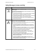
RESTRICTED USE ONLY Fargo Electronics, Inc. Safety Messages (review carefully) Symbol Critical Instructions for Safety purposes Danger: Failure to follow these installation guidelines can result in death or serious injury. Information that raises potential safety issues is indicated by a warning symbol (as shown to the below). Caution: • To prevent personal injury, refer to the following safety messages before performing an operation preceded by this symbol.
RESTRICTED USE ONLY Fargo Electronics, Inc.
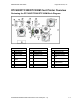
RESTRICTED USE ONLY Fargo Electronics, Inc. Reviewing the DTC400/DTC300/DTC300M Sequence of Operations The following sequence describes a full color print job with magnetic encoding. Step Process 1 The File information is received from the PC 2 Printer checks the installed Ribbon type stored in memory against the Ribbon type command that was sent from the Printer. a. If Ribbon type does not match, the media light will begin flashing. 3 The Card Input Motor and Print Stepper Motor engage.
RESTRICTED USE ONLY Fargo Electronics, Inc. Reviewing the DTC400/DTC300/DTC300M Sequence of Operations (continued) Step Process Step Process 5 The Print Ribbon Drive engages. 6 The Print Ribbon Sensor looks for the color transition from Yellow to Magenta. Print Ribbon Encoder detects number of revolutions required to use an entire color panel. 7 The Print Stepper Motor engages. 8 The Card Feed Sensor detects trailing edge of card.
RESTRICTED USE ONLY Fargo Electronics, Inc. Reviewing the DTC400/DTC300/DTC300M Sequence of Operations (continued) Step Process 23 The Card Feed Stepper Motor engages to queue card for magnetic encoding. 24 The Encoding data is written to the card. 25 The Card Feed Stepper will re-queue card for each verification pass required. 26 After Ribbon advances a few encoder clicks, assume Ribbon free of card. All Stop. 27 Repeat steps 9 through 23 for appropriate number of color/overlay panels.
RESTRICTED USE ONLY Fargo Electronics, Inc. Reviewing the DTC400/DTC300/DTC300M Boot up Sequence Step Process 1 On Power up, the Printer checks the current state of the Card Feed Sensor and the Headlift Sensor. 2 If the Headlift Sensor is found to be open, the Headlift Motor will turn until a closed state is seen. 3 If the Card Feed Sensor is found to be blocked, the Card Feed Stepper will engage to eject the card. DTC400/DTC300/DTC300M Card Printer User Guide (Rev. 1.
RESTRICTED USE ONLY Fargo Electronics, Inc. Section 2: Specifications The purpose of this section is to provide the User with specific information on the Regulatory Compliances, Agency Listings, Technical Specifications and Functional Specifications for the DTC400/DTC300/DTC300M Card Printer User Guide (Rev. 1.1).
RESTRICTED USE ONLY Fargo Electronics, Inc. Regulatory Compliances Term Description CSA The Printer manufacturer has been authorized by UL to represent the Card Printer as CSA Certified under CSA Standard 22.2. File Number: E145118 FCC The Card Printer complies with the requirements in Part 15 of the FCC rules for a Class B digital device. (Note: These requirements are designed to provide reasonable protection against harmful interference in a residential installation.
RESTRICTED USE ONLY Fargo Electronics, Inc. Agency Listings Term Description EMC Standards CE, FCC, CRC c1374, BSMI, ITS (EN 55022 Class B:1998, FCC Class B, EN 55024: 1998). Safety Standards UL IEC 60950-1 (2001), CSA 22.2 No. 60950 and UL-GS (EN 609501:2001). Technical Specifications Type Description Accepted Standard Card Sizes CR-80 (3.375"L x 2.125"W / 85.6mmL x 54mmW) Accepted Card Thickness 20 mil and 30 mil (.030" / .
RESTRICTED USE ONLY Fargo Electronics, Inc. Technical Specifications (continued) Type Description Humidity 20-80% non-condensing Interface USB 1.
RESTRICTED USE ONLY Fargo Electronics, Inc. Technical Specifications (continued) Type Description Supply Voltage 100-240 VAC, .6-1.3 A Supply Frequency 50 Hz/60 Hz System Requirements IBM-PC or compatible; Windows 98SE, Me, 2000 and XP; Pentium™ class 233 MHz computer with 64 MB of RAM or higher, 200 MB free hard disk space or higher, USB 1.1 Weight 15 lbs. / 7 kg DTC400/DTC300/DTC300M Card Printer User Guide (Rev. 1.
RESTRICTED USE ONLY Fargo Electronics, Inc. Visual Security Solutions (Specifications) VeriMarkTM Cards - 2-D holographic foil application VeriMarkTM Cards are a low cost, customized 2-D holographic foil application, that is made in two steps. • The first step is to emboss a base foil 1.9 cm (L) x 1.3 cm (H) onto the surface of a blank white card. • The second step is debossing a custom made dye into the surface of the base foil leaving a customized image, logo or text provided by the customer.
RESTRICTED USE ONLY Fargo Electronics, Inc. VeriMarkTM - Application Specifications VeriMarkTM foils will cover a dimensional area of 1.9 cm length x 1.3 cm height. The exclusive areas are as follows: • VeriMarkTM Card customers will be able to choose 1 of 8 pre-defined placements (corners) via Printer Driver (4 positions) Landscape and (4 Positions) Portrait mode. • VeriMarkTM foil placement will not interfere with card punch slots . • Foil color base is silver; debossed impression is gold foil.
RESTRICTED USE ONLY Fargo Electronics, Inc. Functional Specifications This Card Printer utilizes two different, yet closely related printing technologies to achieve its remarkable direct-to-card print quality for dye-sublimation and resin thermal transfer. The Card Printer will print from any IBM-PC® or compatible running Windows® 98SE, Me, Windows 2000 or Windows XP.
RESTRICTED USE ONLY Fargo Electronics, Inc. Printer Components: Front Cover Components Description Front Cover Opens to allow access to the Ribbon Cartridge. (Note: This cover must be closed in order for the Printer to begin printing.) Printhead The component of the Printer that actually does the printing. (Note: This component is fragile and must not be bumped or touched with anything other than a cleaning swab.) Cancel button The Cancel button turns the Printer ON and OFF.
RESTRICTED USE ONLY Fargo Electronics, Inc. Printer Components: Print Ribbons The Card Printer utilizes both dye-sublimation and/or resin thermal transfer methods to print images directly onto blank cards. Since the dye-sublimation and the resin thermal transfer print methods each provide their own unique benefits, print Ribbons are available in resin-only, dye-sublimation-only and combination dye-sublimation/resin versions.
RESTRICTED USE ONLY Fargo Electronics, Inc. Printer Components: Resin-Only Print Ribbons Resin-only print Ribbons consist of a continuous roll of a single resin color. No protective overlay panel (O) is provided since resin images do not require the protection of such an overlay.
RESTRICTED USE ONLY Fargo Electronics, Inc. Printer Components: Dye-Sublimation Print Ribbons Note that the Printer requires both specialized and authorized print Ribbons in order to print and function properly. Step 1 Procedure Do not run the cards with a contaminated, dull, or uneven surface through the Printer. Caution: Printing onto such cards will ultimately lead to poor print quality and will greatly reduce the life of the Printhead.
RESTRICTED USE ONLY Fargo Electronics, Inc. Printer Components: Dye-Sublimation/Resin Print Ribbons Type Description DyeSublimation/ resin print Ribbon The Dye-Sublimation/resin print Ribbon combines the yellow (Y), magenta (M) and cyan (C) dye-sublimation panels with a resin black (K) panel. By combining both types of Ribbon panels, this Ribbon can be used to print full-color, photo-quality images with the dye-sublimation panels along with sharp, black text and bar codes with the resin black panel.
RESTRICTED USE ONLY Fargo Electronics, Inc. Printer Components: Blank Cards Type Description Card Size The Card Printer accepts standard CR-80 sized and 20 mil. cards (3.370"L x 2.125"W / 85.6mmL x 54mmW) with a thickness of 30 mil (.030"/.762mm). Card Design The Printer will print onto any card with a clean, level and polished PVC surface.
RESTRICTED USE ONLY Fargo Electronics, Inc. Section 3: Setup and Installation Procedures The following guide will walk you through the installation of the DTC400/DTC300/DTC300M Card Printer Driver. • Time Requirement (software): This software installation process will require approximately 2 to 5 minutes (depending on the speed of your PC). • Time Requirement (Printer): The time required to set up a standard DTC400/DTC300/DTC300M Printer would be approximately 5 to 10 minutes.
RESTRICTED USE ONLY Fargo Electronics, Inc. Printing a Test Print Image ___________________________________________ 3-27 Printing a Test Print Image (continued) ________________________________ 3-28 Printer Transport _____________________________________________________ 3-29 Moving the Printer to another location __________________________________ 3-29 DTC400/DTC300/DTC300M Card Printer User Guide (Rev. 1.
RESTRICTED USE ONLY Fargo Electronics, Inc. Printer Setup and Installation Choosing A Good Location Follow these guidelines: • Place the unit in a location with adequate air circulation to prevent internal heat build up. • Use the Printer's dimensions as a guideline for the minimum clearances to the unit. (Note: Allow for adequate clearance in front of the unit to accommodate the unit with its Covers open.
RESTRICTED USE ONLY Fargo Electronics, Inc. Unpacking and Inspection While unpacking your Printer, inspect the carton to ensure that no damage has occurred during shipping. Make sure that all supplied accessories are included with your unit.
RESTRICTED USE ONLY Fargo Electronics, Inc. Reviewing the Printer (front view) Reviewing the Printer (front view; Cartridge being installed) DTC400/DTC300/DTC300M Card Printer User Guide (Rev. 1.
RESTRICTED USE ONLY Fargo Electronics, Inc. Reviewing the LCD (top-front part of Printer) DTC400/DTC300/DTC300M Card Printer User Guide (Rev. 1.
RESTRICTED USE ONLY Fargo Electronics, Inc. Connecting the Printer power Follow this procedure. (Note: Do not connect the Printer’s USB cable until prompted during the Printer Driver installation.) Step Procedure 1 Plug the AC adapter power cable into the back of the Printer. See Display A. 2 Plug the wall power cable into the AC power adapter. 3 Plug the wall power cable into a standard 110VAC power outlet. Display A – Shows back of Printer with AC power cable (below).
RESTRICTED USE ONLY Fargo Electronics, Inc. Installing the Print Ribbon Cartridge The Fargo DTC400/DTC300/DTC300M Card Printer uses a one-piece, disposable Ribbon Cartridge load system. Every full color Ribbon Cartridge contains a 250 “full color card count” Ribbon and a Card Cleaning Roller. Step 1 Procedure To install the Ribbon Cartridge, simply open the front Cover by pressing the black rubber pad or touch pad and lowering the Cover down, as shown below.
RESTRICTED USE ONLY Fargo Electronics, Inc. Installing the Print Ribbon Cartridge (continued) Step 2 Procedure a. Remove the liner on the Card Cleaning Roller before installing the Cartridge, as shown in Display A (upper right arrow of display). b. Remove the Ribbon securing tape, as shown in Display A (middle right arrow of display). 3 Slide the Ribbon Cartridge into the Printer, as shown in this section. 4 Raise the front Cover and press the front Cover’s black rubber pad or touch pad to secure it.
RESTRICTED USE ONLY Fargo Electronics, Inc. Installing the Print Ribbon Cartridge (continued) Display B – Shows direction that Cartridge is inserted in the Printer. DTC400/DTC300/DTC300M Card Printer User Guide (Rev. 1.
RESTRICTED USE ONLY Fargo Electronics, Inc. Installing Blank Cards into the Card Hopper The Fargo DTC400/DTC300/DTC300M Printer is capable of printing single load cards and multiple feed cards (batch mode). • To print using single feed, simply remove all cards from the Card Hopper, leave the Card Hopper door closed and place a card in the single Feed Card Slot (which can be used repeatedly).
RESTRICTED USE ONLY Fargo Electronics, Inc. Installing Blank Cards into the Card Hopper (continued) Display B - Press the Card Hopper Load Lever down. Insert the cards. Here the Lever is still up. Here the Lever is pressed down. Continued on the next page DTC400/DTC300/DTC300M Card Printer User Guide (Rev. 1.
RESTRICTED USE ONLY Fargo Electronics, Inc. Installing Blank Cards into the Card Hopper (continued) Here are the cards ready to insert. Here the Input Hopper Door is closed. Continued on the next page DTC400/DTC300/DTC300M Card Printer User Guide (Rev. 1.
RESTRICTED USE ONLY Fargo Electronics, Inc. Lowering the Card Output Hopper Step 1 Procedure The Fargo DTC400/DTC300/DTC300M comes with a Card Output Hopper (to hold cards after they have been printed). Pull on the Output Hopper and lower its Cover down until it snaps into place. DTC400/DTC300/DTC300M Card Printer User Guide (Rev. 1.
RESTRICTED USE ONLY Fargo Electronics, Inc. Printer Driver Installation Installing the Printer Driver Step 1 Procedure Close all programs and insert the Software Installation CD into your computer’s CD drive. After a few seconds, the CD’s installer program will automatically open. Follow the CD’s on-screen Procedures to complete installation. (Note: If the CD does not automatically open, use “My Computer” or “Windows Explorer” to view the contents of the CD. Then, double-click on the Setup.
RESTRICTED USE ONLY Fargo Electronics, Inc. Installing the Printer Driver (continued) Step 3 Procedure Wait during the installation. Continued on the next page DTC400/DTC300/DTC300M Card Printer User Guide (Rev. 1.
RESTRICTED USE ONLY Fargo Electronics, Inc. Installing the Printer Driver (continued) Step 4 Procedure Click on the Next button to continue with the Setup program. Continued on the next page DTC400/DTC300/DTC300M Card Printer User Guide (Rev. 1.
RESTRICTED USE ONLY Fargo Electronics, Inc. Installing the Printer Driver (continued) Step 5 Procedure Read the License Agreement. Select the I accept the terms of the license agreement option and click Next to continue. Continued on the next page DTC400/DTC300/DTC300M Card Printer User Guide (Rev. 1.
RESTRICTED USE ONLY Fargo Electronics, Inc. Installing the Printer Driver (continued) Step 6 Procedure a. Select the Complete option to install the following components: • Printer Driver Software • Printer Driver User’s Guide • Fargo Diagnostics Utility (Note: Selecting Custom will provide the option to select which components to install.) b. Click Next to continue. Continued on the next page DTC400/DTC300/DTC300M Card Printer User Guide (Rev. 1.
RESTRICTED USE ONLY Fargo Electronics, Inc. Installing the Printer Driver (continued) Step 7 Procedure Click Install to begin the installation. Continued on the next page DTC400/DTC300/DTC300M Card Printer User Guide (Rev. 1.
RESTRICTED USE ONLY Fargo Electronics, Inc. Installing the Printer Driver (continued) Step 8 Procedure Select the port that your Printer is connected to at this time. Click on the OK button and continue with the installation. Continued on the next page DTC400/DTC300/DTC300M Card Printer User Guide (Rev. 1.
RESTRICTED USE ONLY Fargo Electronics, Inc. Installing the Printer Driver (continued) Step 9 Procedure a. Connect the USB cable to the Printer. b. Turn ON the Printer at this time if it is not already ON. Continued on the next page DTC400/DTC300/DTC300M Card Printer User Guide (Rev. 1.
RESTRICTED USE ONLY Fargo Electronics, Inc. Installing the Printer Driver (continued) Step 10 Procedure Wait while the Driver components are being copied to your PC. Continued on the next page DTC400/DTC300/DTC300M Card Printer User Guide (Rev. 1.
RESTRICTED USE ONLY Fargo Electronics, Inc. Installing the Printer Driver (continued) Step 11 Procedure Click on the Finish button to complete the Setup, as shown below. Continued on the next page DTC400/DTC300/DTC300M Card Printer User Guide (Rev. 1.
RESTRICTED USE ONLY Fargo Electronics, Inc. Installing the Printer Driver (continued) Step 12 Procedure a. Click on the Yes button to exit the installer, as shown below. b. Click on the No button to return to the installer’s main menu to install additional software components. Continued on the next page DTC400/DTC300/DTC300M Card Printer User Guide (Rev. 1.
RESTRICTED USE ONLY Fargo Electronics, Inc. Installing the Printer Driver (continued) Step 13 Procedure You have completed the installation. DTC400/DTC300/DTC300M Card Printer User Guide (Rev. 1.
RESTRICTED USE ONLY Fargo Electronics, Inc. Printing a Test Print Image Step 1 Procedure a. From your computer’s startup menu, select Settings > Printers and Faxes (Windows XP) or > Printers (Windows 98SE, Me and 2000). b. Double click on the DTC400/DTC300/DTC300M Card Printer under the Printers window. c. Select Printing Preferences under the Printer drop-down menu. This will bring up the DTC400/DTC300/DTC300M Printing Preferences window. 2 a.
RESTRICTED USE ONLY Fargo Electronics, Inc. Printing a Test Print Image (continued) Step 3 Procedure This completes the DTC400/DTC300/DTC300M Card Printer/Encoder Installation Guide. For additional help regarding the Test Print and other related items please see the DTC400/DTC300/DTC300M Card Printer User Guide located under Start > Programs > Fargo. DTC400/DTC300/DTC300M Card Printer User Guide (Rev. 1.
RESTRICTED USE ONLY Fargo Electronics, Inc. Printer Transport Moving the Printer to another location Step Procedure 1 The Printer can be transported by gripping it under the back lid, as shown in the photo below. 2 You have completed the setup and installation procedures in this section. DTC400/DTC300/DTC300M Card Printer User Guide (Rev. 1.
RESTRICTED USE ONLY Fargo Electronics, Inc. Section 4: General Troubleshooting This section provides Troubleshooting procedures for this Printer for Communication Errors, Card Feed Errors, Print Process Errors, Card Jam Errors, Encoding Errors and Diagnosing Image Problems.
RESTRICTED USE ONLY Fargo Electronics, Inc.
RESTRICTED USE ONLY Fargo Electronics, Inc. Safety Messages (review carefully) Symbol Critical Instructions for Safety purposes Danger: Failure to follow these installation guidelines can result in death or serious injury. Information that raises potential safety issues is indicated by a warning symbol (as shown to the below). Caution: • To prevent personal injury, refer to the following safety messages before performing an operation preceded by this symbol.
RESTRICTED USE ONLY Fargo Electronics, Inc. Communications Errors Resolving the Communication Errors Symptom(s): Incorrect output, communications error on PC or Printer, stalling, no response from Printer, no job printed, “paper out” error. Step 1 2 Procedure Confirm that the system meets the minimum requirements, as shown here: • IBM-PC or compatible.
RESTRICTED USE ONLY Fargo Electronics, Inc. Resolving the Communication Errors (continued) Step 4 Procedure Determine whether there is adequate hard Drive space. (Note: A large volume of temporary files on the computer can cause communications errors.) a. Access the temporary files by following this process: • Search for all folders called TEMP. Once found, clear out the contents of the folders.
RESTRICTED USE ONLY Fargo Electronics, Inc. Print Process Errors All Troubleshooting procedures assume that only factory-authorized supplies are in use in the Printer. Resolving a Card Not Fed Error (Cards will not feed off the Hopper) Step 1 Procedure Review the following information. • Symptom: Cards will not feed at all.
RESTRICTED USE ONLY Fargo Electronics, Inc. Resolving a Card Not Fed Error (Cards will not feed off the Hopper) (continued) Step 2 Procedure Check the card quality / loading. a. Remove cards from the Card Hopper. b. Ensure that the cards are not sticking together by fanning them out and then lining them back together in straight deck. c. Press the Card Hopper Load Lever down until the Card Tray locks into place. d. Load up to 100 cards into the Hopper with the print side down. e.
RESTRICTED USE ONLY Fargo Electronics, Inc. Resolving a Card Not Fed Error (Cards will not feed off the Hopper) (continued) Step 6 Procedure Check Hopper Tray Spring Tension. a. Open Card Hopper Cover. b. Using the Fargo Diagnostic utility, send a test print to the Printer. See the Using the Diagnostic Utility tabs. c. When the Card Hopper Feed Roller engages, push up on the Card Hopper Tray. g. If the cards feed, replace the Card Hopper Lift Spring. d.
RESTRICTED USE ONLY Fargo Electronics, Inc. Resolving a Card Not Fed Error (Two (2) or more card feed at the same time) All Troubleshooting procedures assume that only factory-authorized supplies are in use in the Printer. Step 1 Procedure Review the following information. • Symptoms: Two or more cards feed at the same time causing the cards to jam at the Card Hopper Roller. Printer is out of cards.
RESTRICTED USE ONLY Fargo Electronics, Inc. Resolving a Card Not Fed Error (Two (2) or more card feed at the same time) (continued) Step 2 Procedure Check card quality / loading. a. Remove cards from the Card Hopper. b. Ensure that the cards are not sticking together by fanning them out and then lining them back together in straight deck. c. Press the Card Hopper Load Lever down until the Card Tray locks into place. d. Load up to 100 cards into the Hopper with the print side down. e.
RESTRICTED USE ONLY Fargo Electronics, Inc. Resolving a Ribbon RFID Error (Ribbon RFID Antenna is Corrupted) All Troubleshooting procedures assume that only factory-authorized supplies are in use in the Printer. Step 1 Procedure Review the following information. • Symptom: Printer RFID Sensor does not detect a recognizable signal from the Ribbon. • Printer Error State: The Ribbon tag information is corrupted or incorrect.
RESTRICTED USE ONLY Fargo Electronics, Inc. Resolving a Ribbon RFID Error (Ribbon RFID Antenna is Corrupted) (continued) Step 2 Procedure Replace the Print Ribbon a. Replace the Print Ribbon Cartridge. b. Press on the Resume button. c. If the error continues, see Resolving the Ribbon RFID Error (Ribbon RFID Sensor is Corrupted) in this section. DTC400/DTC300/DTC300M Card Printer User Guide (Rev. 1.
RESTRICTED USE ONLY Fargo Electronics, Inc. Resolving a Ribbon RFID Error (Ribbon RFID Sensor is Corrupted) All Troubleshooting procedures assume that only factory-authorized supplies are in use in the Printer. Step 1 2 Procedure Review the following information. • Symptom: Printer RFID Sensor does not detect a recognizable signal from the Ribbon. • Printer Error State: The Ribbon tag information is corrupted or incorrect.
RESTRICTED USE ONLY Fargo Electronics, Inc. Resolving the Mag Verify Error All Troubleshooting procedures assume that only factory-authorized supplies are in use in the Printer. Step 1 Procedure Review the following information. • Symptom: The Printer is unable to verify encoded data. • Printer Error State: The Printer is unable to verify encoded data.
RESTRICTED USE ONLY Fargo Electronics, Inc. Resolving a Mag Verify Error (continued) Step Procedure 2 Check to ensure that the cards are loaded with the Magnetic Stripe facing Up and towards the front of the Printer. 3 a. Press on the Resume button. b. If the error continues continue to step 4 4 Verify the Driver settings if cards are loaded properly. See the Using the Magnetic Encoding tab procedure in . 5 Verify that data is being encoded to the Magnetic Stripe. a.
RESTRICTED USE ONLY Fargo Electronics, Inc. Resolving a Mag Verify Error (continued) Step 6 Procedure Verify that the coercivity of the cards matches the Driver Settings. DTC400/DTC300/DTC300M Card Printer User Guide (Rev. 1.
RESTRICTED USE ONLY Fargo Electronics, Inc. Resolving the No Mag Installed Error All Troubleshooting procedures assume that only factory-authorized supplies are in use in the Printer. Step 1 Procedure Review the following information. • Symptom: There is not Magnetic Encoder installed. • Printer Error State: A print job with Magnetic encoding was sent with no Magnetic encoder installed in the Printer.
RESTRICTED USE ONLY Fargo Electronics, Inc. Resolving a No Mag Installed Error (continued) Step Procedure 2 Press the Cancel Print button on the Driver Monitor Error Display Message. 3 Reboot the Printer by cycling the power. 4 Verify that the Printer has a Magnetic Encoder installed. a. Open the front cover. b. Remove the Magnetic Module cover screw. c. Remove the Magnetic Module cover. d. Verify that the Printer has a Magnetic Module installed.
RESTRICTED USE ONLY Fargo Electronics, Inc. Resolving a Ribbon Sensor Error (Ribbon Miscue) All Troubleshooting procedures assume that only factory-authorized supplies are in use in the Printer. Step 1 Procedure Review the following information. • Symptom: The Printer rolls through Ribbon and errors out • Printer Error State: The Printer cannot find the next panel on the Ribbon.
RESTRICTED USE ONLY Fargo Electronics, Inc. Resolving a Ribbon Sensor Error (Ribbon Miscue) (continued) Step 2 Procedure Open the front cover and remove the Ribbon Cartridge. a. Check that the Ribbon is in good condition and not wrinkled or broken. a. If Ribbon is broke or wrinkled, repair the Ribbon and wind up the takeup roll 4-color panels past the damaged area. 3 Press on the Resume button. If the issue persists, continue to Step 4. 4 Replace the Ribbon Cartridge. a. Press on the Resume button.
RESTRICTED USE ONLY Fargo Electronics, Inc. Resolving a Ribbon Break Jam Error All Troubleshooting procedures assume that only factory-authorized supplies are in use in the Printer. Step 1 Procedure Review the following information.
RESTRICTED USE ONLY Fargo Electronics, Inc. Resolving a Ribbon Break Jam Error (continued) Step 2 3 Procedure Open the front cover and remove the Ribbon Cartridge. • If Ribbon is broken, continue to Step 3. • If Ribbon is in good condition, continue to Step 6. Adjust the print offset (See Using the Print Top of Form Option) If the issue persists, continue to Step 4. 4 Repair the Ribbon and wind up the take-up roll 4 color panels past the damage area. a. Press on the Resume button.
RESTRICTED USE ONLY Fargo Electronics, Inc. Resolving a Ribbon Out Error All Troubleshooting procedures assume that only factory-authorized supplies are in use in the Printer. Step 1 2 Procedure Review the following information. • Symptom: Printer will not print. • Printer Error State: The Ribbon Sensor has detected the End Of Ribbon mark • LCD Error Display: Ribbon Out • Driver Monitor Error Display: Ribbon Out Replace the Ribbon Cartridge a. Press on the Resume button.
RESTRICTED USE ONLY Fargo Electronics, Inc. Resolving a No Ribbon Installed Error All Troubleshooting procedures assume that only factory-authorized supplies are in use in the Printer. Step 1 Procedure Review the following information.
RESTRICTED USE ONLY Fargo Electronics, Inc. Resolving a No Ribbon Installed Error (continued) Step 2 Procedure Verify that a Ribbon Cartridge is installed in the Printer. a. Press on the Resume button. If the issue persist, continue to Step 3. 3 4 Remove the rear cover and check that the Ribbon RFID cable is securely connected to the Main Board (J-5) and the RFID Sensor. • If the connections are loose, reattach • . Press on the Resume button.
RESTRICTED USE ONLY Fargo Electronics, Inc. Resolving a Invalid Ribbon Error All Troubleshooting procedures assume that only factory-authorized supplies are in use in the Printer. Step 1 Procedure Review the following information. • Symptom: Printer errors out as soon as it receives data from the PC • Printer Error State: The Ribbon installed does not match the Printer model.
RESTRICTED USE ONLY Fargo Electronics, Inc. Resolving a Invalid Ribbon Error (continued) Step Procedure 2 Verify that the Ribbon Cartridge installed is designed for the correct Printer model. 3 Press on the Resume button. If the issue persists, continue to Step 4. 4 5 Remove the rear cover and check that the Ribbon RFID cable is securely connected to the Main Board (J-5) and the RFID Sensor. • If the connections are loose, reattach • Press on the Resume button..
RESTRICTED USE ONLY Fargo Electronics, Inc. Resolving a Wrong Ribbon Error All Troubleshooting procedures assume that only factory-authorized supplies are in use in the Printer. Step 1 Procedure Review the following information.
RESTRICTED USE ONLY Fargo Electronics, Inc. Resolving a Wrong Ribbon Error (continued) Step 2 Procedure Verify the Driver settings are correct. a. Open the Printer Control Panel from the Computer. • If using Windows 98SE, Me, right click on the DTC400/DTC300 Card Printer Icon and select Properties. • If using Windows 2000/XP, right click on the DTC400/DTC300 Card Printer and select Printing Preferences. b. Click on the Device Option tab. c. Click on the auto select button. d.
RESTRICTED USE ONLY Fargo Electronics, Inc. Resolving a Card Jam Error All Troubleshooting procedures assume that only factory-authorized supplies are in use in the Printer. Step 1 Procedure Review the following information. • Symptom: Card is jammed. • Printer Error State: Card TOF Sensor is detecting no card motion • LCD Error Display: Card Jam • Driver Monitor Error Display: Card Jam Continued on the next page DTC400/DTC300/DTC300M Card Printer User Guide (Rev. 1.
RESTRICTED USE ONLY Fargo Electronics, Inc. Resolving a Card Jam Error (continued) Step 2 Procedure Look for a jammed card in the Printer. a. Open the Printer’s front cover. b. Remove the Ribbon Cartridge from the Printer. c. Check to see if a card is jammed in the print station of the Printer. d. If a card is found in the print station, continue to Step 3. e. If no card was found in the print station, continue to Step 4. 3 Clearing a jammed card. a.
RESTRICTED USE ONLY Fargo Electronics, Inc. Resolving a Headlift Motor or Sensor Error All Troubleshooting procedures assume that only factory-authorized supplies are in use in the Printer. Step Procedure 1 Review the following information.
RESTRICTED USE ONLY Fargo Electronics, Inc. Resolving a Headlift Motor or Sensor Error (continued) Step Procedure 2 Press the Cancel Print button on the Driver Monitor Error Display Message. 3 Reboot the Printer by cycling the power. 4 Cycle the Headlift Motors. a. Use the Fargo Diagnostic utility to cycle the Printhead to ensure proper printhead operation. See the Using the Diagnostic Utility tabs. a. Verify that the Headlift Motor turns. b. If the Motor does not turn or jams, continue to Step 5.
RESTRICTED USE ONLY Fargo Electronics, Inc. Resolving the Cover Open Error Message All Troubleshooting procedures assume that only factory-authorized supplies are in use in the Printer. Step 1 2 Procedure Review the following information. • Symptom: The Printer errors immediately after sending a print job, or the Rollers do not operate by pressing the cottons on the front panel (when the cover is open).
RESTRICTED USE ONLY Fargo Electronics, Inc. Resolving the Blank Output issues All Troubleshooting procedures assume that only factory-authorized supplies are in use in the Printer. Step 1 2 Procedure Review the following information. • Symptom: A card is ejected blank (that should be printed). • Printer Error State: None • LCD Error Display: None • Driver Monitor Error Display: None Run a self-test. a. Clear any card jams. b. Unplug power from the Printer. c.
RESTRICTED USE ONLY Fargo Electronics, Inc. Resolving the Blank Output issues (continued) Step 4 Procedure Adjust the placement. a. Reset the Printer to clear any Error Messages by removing the power and reapplying it. b. Open the Printer Control Panel from the Computer. • If using Windows 98SE, Me, right click on the DTC400/DTC300/DTC300M Card Printer Icon and select Properties. • If using Windows 2000/XP, right click on the DTC400/DTC300/DTC300M Card Printer and select Printing Preferences. c.
RESTRICTED USE ONLY Fargo Electronics, Inc. Resolving the Blank Output issues (continued) Step 6 Procedure Ensure that the proper voltage is being applied to the Printhead. a. Remove the back cover. b. Using a Digital Voltmeter, connect the negative lead to ground. c. Probe Pins 1 to 5 of the Printhead power connection on J16. d. Ensure that a voltage between 22 to 23 VDC is read on each pin. • If less than 22 volts is read on any of the pins, replace the Printhead.
RESTRICTED USE ONLY Fargo Electronics, Inc. Diagnosing Image Problems Resolving the Pixel Failure problems All Troubleshooting procedures assume that only factory-authorized supplies are in use in the Printer. Step 1 Procedure Review the following information. • Symptom: A thin line or scratch travels the entire length of the card (See sample image below). • Printer Error State: None • LCD Error Display: None • Driver Monitor Error Display: None 2 Check the card stock for scratches.
RESTRICTED USE ONLY Fargo Electronics, Inc. Resolving the Card Surface Debris problems All Troubleshooting procedures assume that only factory-authorized supplies are in use in the Printer. Step 1 Procedure Review the following information. • Symptom: Prints have spots (white or colored voids) and/or dust on them (See sample image below). • Printer Error State: None • LCD Error Display: None • Driver Monitor Error Display: None 2 Ensure the cards are clean and stored in a dust-free environment.
RESTRICTED USE ONLY Fargo Electronics, Inc. Resolving the Incorrect Image Darkness problems All Troubleshooting procedures assume that only factory-authorized supplies are in use in the Printer. Step 1 Procedure Review the following information. • Symptom: Printed cards are too dark or too light. • Printer Error State: None • LCD Error Display: None • Driver Monitor Error Display: None 2 Run a self-test to ensure that the issue is not with the Driver settings.
RESTRICTED USE ONLY Fargo Electronics, Inc. Resolving the Incorrect Image Darkness problems (continued) Step 4 Procedure Correct the Image Darkness. See the Using the Image Darkness option procedure. DTC400/DTC300/DTC300M Card Printer User Guide (Rev. 1.
RESTRICTED USE ONLY Fargo Electronics, Inc. Resolving Ribbon Wrinkle problems All Troubleshooting procedures assume that only factory-authorized supplies are in use in the Printer. Step 1 Procedure Review the following information. • Symptom: Printed cards have off-colored lines or streaks on them. • Printer Error State: None • LCD Error Display: None • Driver Monitor Error Display: None 2 Confirm that the Printer is using the most current Driver via: http://www.fargo.
RESTRICTED USE ONLY Fargo Electronics, Inc. Resolving Ribbon Wrinkle problems (continued) Step 4 Procedure Reduce the Image Darkness. See the Using the Image Darkness option procedure. DTC400/DTC300/DTC300M Card Printer User Guide (Rev. 1.
RESTRICTED USE ONLY Fargo Electronics, Inc. Resolving the Excessive Resin Printing problems All Troubleshooting procedures assume that only factory-authorized supplies are in use in the Printer. Step 1 2 Procedure Review the following information. • Symptom: Black resin text and barcodes appear smeared or too thick. • Printer Error State: None • LCD Error Display: None • Driver Monitor Error Display: None Reduce the Resin Heat setting within the Image Color tab of the Printer Driver.
RESTRICTED USE ONLY Fargo Electronics, Inc. Resolving the Excessive Resin Printing problems (continued) Step 3 Procedure Reduce the Image Darkness. See the Using the Image Darkness option procedure. DTC400/DTC300/DTC300M Card Printer User Guide (Rev. 1.
RESTRICTED USE ONLY Fargo Electronics, Inc. Resolving the Incomplete Resin Printing problems All Troubleshooting procedures assume that only factory-authorized supplies are in use in the Printer. Step 1 Procedure Review the following information. • Symptom: Black resin text and barcodes appear faded or too light. • Printer Error State: None • LCD Error Display: None • Driver Monitor Error Display: None 2 Increase the Resin Heat setting within the Image Color tab of the Printer Driver.
RESTRICTED USE ONLY Fargo Electronics, Inc. Resolving the Image Placement problems All Troubleshooting procedures assume that only factory-authorized supplies are in use in the Printer. This procedure is used to adjust the position of the card in the Print driver and does not change the internal settings of the printer. See Using the Printer Calibration Utility for instructions on changing the printers internal settings. Step 1 2 Procedure Review the following information.
RESTRICTED USE ONLY Fargo Electronics, Inc. Resolving the Image Placement problems (continued) Step 3 Procedure Verify if the Horizontal Image Position Setting is set correctly or incorrectly. See the graphic below. • If the white border is on the leading edge of the card, adjust the Horizontal value by +2. • If the white border is on the trailing edge of the card, adjust the Horizontal value by -2. a. Click on OK. b. Run a self-test. c.
RESTRICTED USE ONLY Fargo Electronics, Inc. Resolving the Image Placement problems (continued) Step 4 Procedure Verify if the Vertical Image Position Setting is set correctly or incorrectly. See the graphic below. • If the white border is on the top edge of the card, adjust the Vertical value by +2. • If the white border is on the botom edge of the card, adjust the Vertical value by -2. a. Click on OK. b. Run a self-test. c. If the white border is diminished, continue the adjustment until it is gone.
RESTRICTED USE ONLY Fargo Electronics, Inc. Resolving the Poor Image Quality problems All Troubleshooting procedures assume that only factory-authorized supplies are in use in the Printer. Step 1 2 Procedure Review the following information. • Symptom: Photos on the cards look pixilated or grainy, as shown below.
RESTRICTED USE ONLY Fargo Electronics, Inc. Running the Self Test Perform a self-test after (a) an initial setup of the Printer, (b) a calibration procedure has been conducted, or (c) a part has been replaced to check for proper Printer operation. Step 1 Procedure Verify that a full-color or Premium Resin Ribbon Cartridge is installed and that cards are properly loaded. Caution: If the power is ON, disconnect the Power Cable from the Printer’s rear panel. 2 Press and hold the Pause/Resume button.
RESTRICTED USE ONLY Fargo Electronics, Inc. Running the Standard Self Test Print Display A Full Color Test Print Display B Resin Test Print (insert image of resin test print) DTC400/DTC300/DTC300M Card Printer User Guide (Rev. 1.
RESTRICTED USE ONLY Fargo Electronics, Inc. Running the Magnetic Self Test (HiCo Only) Perform a self-test after (a) an initial setup of the Printer, (b) a calibration procedure has been conducted, or (c) a part has been replaced to check for proper Printer operation. Step 1 Procedure Remove Ribbon Cartridge from the Printer and close the front cover Caution: If the power is ON, disconnect the Power Cable from the Printer’s rear panel. 2 Press and hold the Pause/Resume button.
RESTRICTED USE ONLY Fargo Electronics, Inc. Section 5: Printer Adjustments See this section for printer adjustments.
RESTRICTED USE ONLY Fargo Electronics, Inc.
RESTRICTED USE ONLY Fargo Electronics, Inc.
RESTRICTED USE ONLY Fargo Electronics, Inc. Safety Messages (review carefully) Symbol Critical Instructions for Safety purposes Danger: Failure to follow these installation guidelines can result in death or serious injury. Information that raises potential safety issues is indicated by a warning symbol (as shown to the below). Caution: • To prevent personal injury, refer to the following safety messages before performing an operation preceded by this symbol.
RESTRICTED USE ONLY Fargo Electronics, Inc. DTC400/DTC300 Print Driver Options Reviewing DTC400, DTC300 and DTC300M Printer Drivers The functionality of the DTC400, DTC300 and DTC300M Printer Drivers is identical. The window title reflects the specific Printer Driver in use as shown in this introductory section. Reviewing DTC400 Printer Drivers This section applies to the DTC400 Printer. DTC400/DTC300/DTC300M Card Printer User Guide (Rev. 1.
RESTRICTED USE ONLY Fargo Electronics, Inc. Reviewing DTC300 Printer Driver This section applies to the DTC300 Printer. DTC400/DTC300/DTC300M Card Printer User Guide (Rev. 1.
RESTRICTED USE ONLY Fargo Electronics, Inc. Reviewing DTC300M Printer Drivers This section applies to the DTC300M Printer. DTC400/DTC300/DTC300M Card Printer User Guide (Rev. 1.
RESTRICTED USE ONLY Fargo Electronics, Inc. Using the Card tab Adjusting the Card Size Option Step 1 Description Click on the inches or mm option to choose the desired unit of measurement. (Note No.1: When designing a card format, always set the card size or page size within the card design program to the exact dimensions of a CR-80 card.) (Note No.2: The Card Size indicates that the Printer accepts standard, "credit card" size CR-80 (ISO ID-1) cards.
RESTRICTED USE ONLY Fargo Electronics, Inc. Adjusting the Orientation Option Step 1 Description Select Portrait under Orientation to cause the card to print in a vertical orientation. OR Select Landscape under Orientation to cause the card to print in a horizontal orientation. (Note: An icon illustrating a printed card helps represent the difference between the two.) DTC400/DTC300/DTC300M Card Printer User Guide (Rev. 1.
RESTRICTED USE ONLY Fargo Electronics, Inc. Selecting the number of copies Step 1 Description Select the number of copies by clicking on the UP or DOWN arrows, as shown below. DTC400/DTC300/DTC300M Card Printer User Guide (Rev. 1.
RESTRICTED USE ONLY Fargo Electronics, Inc. Using the Diagnostics button under the Card tab Step 1 Description Click on the Diagnostic button to bring up the Fargo Diagnostics Utility window. See the Section 9: Diagnostic Tool Utility. DTC400/DTC300/DTC300M Card Printer User Guide (Rev. 1.
RESTRICTED USE ONLY Fargo Electronics, Inc. Using the Clean Printer Option Step Description 1 Click on the Clean Printer button to display the Clean Printer Utility window. 2 Remove all cards from the Card Hopper and close the Hopper door. 3 Open the Front Cover and remove the Ribbon Cartridge. 4 Remove the paper backing from both sides of the Cleaning Card. 5 Place the Cleaning card into the Single Feed Slot. DTC400/DTC300/DTC300M Card Printer User Guide (Rev. 1.
RESTRICTED USE ONLY Fargo Electronics, Inc. Using the Clean Printer Option (Continued) Step Description 6 Click on the Clean button at the bottom of the window. (Note: The Printer will begin to feed the cleaning card through the card path.) 7 Reinsert the print Ribbon and cards after the cleaning procedure has completed. DTC400/DTC300/DTC300M Card Printer User Guide (Rev. 1.
RESTRICTED USE ONLY Fargo Electronics, Inc. Using the Test Print button Step 1 Description Click on the Test Print button to send a simple self-test print to the Printer. • Ensure that a YMCKO Ribbon is installed for DTC400/DTC300 or a Premium Resin Ribbon installed for DTC300M. • Ensure that the computer is effectively communicating with the Printer and that the Printer is functioning properly. DTC400/DTC300/DTC300M Card Printer User Guide (Rev. 1.
RESTRICTED USE ONLY Fargo Electronics, Inc. Using the About button Step 1 Description Click on the About button to open a dialog box containing the copyright and version, date code information about this Printer Driver software. DTC400/DTC300/DTC300M Card Printer User Guide (Rev. 1.
RESTRICTED USE ONLY Fargo Electronics, Inc. Using the Device Options tab (DTC400/DTC300) Adjusting the Ribbon Type option Use the Ribbon Type option to select print Ribbons. Step 1 Description Select the appropriate print Ribbon Type option from the dropdown menu for the type of print Ribbon in use. • YMCKO – Full Color/Resin Black/Overlay • K – Standard Resin • K – Premium Resin • Colored Resin • Metallic Resin • KO – Premium Resin/Overlay DTC400/DTC300/DTC300M Card Printer User Guide (Rev.
RESTRICTED USE ONLY Fargo Electronics, Inc. Selecting the Auto Ribbon Select option Step 1 Description Click on the Auto Ribbon Select button to verify that the Ribbon type selected matches the Ribbon installed in the Printer. (Note: The Printer Driver will change the Ribbon type to the correct setting or validate. It will also display a dialog that it has changed the current setting or that the current Ribbon type is correct.) DTC400/DTC300/DTC300M Card Printer User Guide (Rev. 1.
RESTRICTED USE ONLY Fargo Electronics, Inc. Adjusting the Color Matching option Use the Color Matching dropdown menu to choose the color matching options which best fits the print job requirements. Step 1 Description Select None for print speed versus print color or for use of third party color matching software.
RESTRICTED USE ONLY Fargo Electronics, Inc. Adjusting for the Resin Dither Select the appropriate dither method according to the type of image to be printed. This option affects objects printed with a resin-only print Ribbon. Step 1 Procedure Select Optimized for Photo when printing photo quality images with resin. OR Select Optimized for Graphics when printing drawings and graphics (e.g., clipart, logos, etc.) with resin. DTC400/DTC300/DTC300M Card Printer User Guide (Rev. 1.
RESTRICTED USE ONLY Fargo Electronics, Inc. Using the Rotate Image 180 Degrees option Use this option to rotate the image on the front of the card 180 degrees when printed. Step 1 Description Select this option to change the position of the printed image in relation to the set location of a card's Magnetic Stripe or smart chip. DTC400/DTC300/DTC300M Card Printer User Guide (Rev. 1.
RESTRICTED USE ONLY Fargo Electronics, Inc. Using the Disable Printing option Use this option to disable the printing capabilities of the Printer, yet still allows the Printer to encode cards. Step 1 Description Select this option to encode or re-encode cards without wasting additional time, effort, or printing supplies. (Note: When this option is selected, no print data will not be sent to the Printer. All encoding instructions will be sent according to how they are configured within the software.
RESTRICTED USE ONLY Fargo Electronics, Inc. Using the Device Options tab (DTC300M) Adjusting the Ribbon Type option Use the Ribbon Type option to select print Ribbons. Step 1 Description Select the appropriate print Ribbon Type option from the dropdown menu for the type of print Ribbon in use. • K – Standard Resin • K – Premium Resin • Colored Resin • Metallic Resin • KO – Premium Resin/Overlay DTC400/DTC300/DTC300M Card Printer User Guide (Rev. 1.
RESTRICTED USE ONLY Fargo Electronics, Inc. Selecting the Auto Ribbon Select option Step 1 Description Click on the Auto Ribbon Select button to verify that the Ribbon type selected matches the Ribbon installed in the Printer. (Note: The Printer Driver will change the Ribbon type to the correct setting or validate. It will also display a dialog that it has changed the current setting or that the current Ribbon type is correct.) DTC400/DTC300/DTC300M Card Printer User Guide (Rev. 1.
RESTRICTED USE ONLY Fargo Electronics, Inc. Adjusting for the Resin Dither Select the appropriate dither method according to the type of image to be printed. This option affects objects printed with a resin-only print Ribbon. Step 1 Procedure Select Optimized for Photo when printing photo quality images with resin. OR Select Optimized for Graphics when printing drawings and graphics (e.g., clipart, logos, etc.) with resin. DTC400/DTC300/DTC300M Card Printer User Guide (Rev. 1.
RESTRICTED USE ONLY Fargo Electronics, Inc. Using the Rotate Image 180 Degrees option Use this option to rotate the image on the front of the card 180 degrees when printed. Step 1 Description Select this option to change the position of the printed image in relation to the set location of a card's Magnetic Stripe or smart chip. DTC400/DTC300/DTC300M Card Printer User Guide (Rev. 1.
RESTRICTED USE ONLY Fargo Electronics, Inc. Using the Disable Printing option Use this option to disable the printing capabilities of the Printer, yet still allows the Printer to encode cards. Step 1 Description Select this option to encode or re-encode cards without wasting additional time, effort, or printing supplies. (Note: When this option is selected, no print data will not be sent to the Printer. All encoding instructions will be sent according to how they are configured within the software.
RESTRICTED USE ONLY Fargo Electronics, Inc. Using the Resin Heat (K) option Use this option to control the amount of heat the Printer uses when printing with the resin black panel(s) of a full-color Ribbon or when printing with a resin-only Ribbon by adjusting the Resin Heat slide. Step 1 Procedure Move the slide to the left to cause less heat to be used in the printing process, causing resin images to be lighter or less saturated. OR Move the slide to the right to cause more heat to be used.
RESTRICTED USE ONLY Fargo Electronics, Inc. Using the Overlay Heat (O) option Use this option to control the amount of heat the Printer uses when printing with the overlay panel of a Ribbon. Step 1 Procedure Move the slide to the left to cause less heat to be used in the printing process. (Note: Certain card types may need additional heat for better transfer of the overlay material.) OR Move the slide to the right to cause more heat to be used.
RESTRICTED USE ONLY Fargo Electronics, Inc. Using the Image Color tab (DTC400/DTC300) Step Procedure 1 Select the Algebraic color matching option and then use this option to control the Contrast and Gamma of the printed image, as well as the individual color balance of Yellow, Magenta and Cyan. (Note: In most cases, the default settings of these options will suffice.
RESTRICTED USE ONLY Fargo Electronics, Inc. Using the Resin Heat (K) option Use this option to control the amount of heat the Printer uses when printing with the resin black panel(s) of a full-color Ribbon or when printing with a resin-only Ribbon by adjusting the Resin Heat slide. Step 1 Procedure Move the slide to the left to cause less heat to be used in the printing process, causing resin images to be lighter or less saturated.
RESTRICTED USE ONLY Fargo Electronics, Inc. Using the Overlay Heat (O) option Use this option to control the amount of heat the Printer uses when printing with the overlay panel of a Ribbon. Step 1 Procedure Move the slide to the left to cause less heat to be used in the printing process. (Note: Certain card types may need additional heat for better transfer of the overlay material.) OR Move the slide to the right to cause more heat to be used.
RESTRICTED USE ONLY Fargo Electronics, Inc. Using the Color Matching option and Default button Step 1 Procedure To return all options to their factory settings, click on the Default button. DTC400/DTC300/DTC300M Card Printer User Guide (Rev. 1.
RESTRICTED USE ONLY Fargo Electronics, Inc. Using the Calibrate tab Use the Calibrate tab to (a) control the position of the printable area in relation to the card, (b) calibrate Sensors and (c) adjust the internal Printer settings that are customized for every Printer and saved directly within the Printer's memory. DTC400/DTC300/DTC300M Card Printer User Guide (Rev. 1.
RESTRICTED USE ONLY Fargo Electronics, Inc. Using the Image Position Controls Use the Image Position controls to adjust the position of the overall print area to be precisely centered on a card. Step 1 Procedure Click on the Vertical and Horizontal adjustment arrows to adjust the Image Position values. • When adjusting these values, keep in mind that cards always remain in the same position while moving through the Printer, regardless of image orientation.
RESTRICTED USE ONLY Fargo Electronics, Inc. Using Image Position controls (continued) Review the Image Position diagram, which displays how the printed image will move in relation to the fixed card position as positive and negative image placement values are entered. Step 2 Procedure Use the Vertical adjustment to move the image: • Move toward the rear of the Printer if a positive number is entered. • Move toward the front of the Printer if a negative number is entered.
RESTRICTED USE ONLY Fargo Electronics, Inc. Using the Sensors button Use the Sensors button to bring up a separate dialog box for calibrating the Printer's Ribbon Sensor (see instructions in the Calibration window below). DTC400/DTC300/DTC300M Card Printer User Guide (Rev. 1.
RESTRICTED USE ONLY Fargo Electronics, Inc. Using the Settings button Use the Settings button (see above) to bring up a separate dialog box for adjusting the internal Printer settings, which are customized for every Printer at the factory and saved directly within the Printer's memory. (Note: You can select the Restore Defaults to restore the internal default settings.) See the Using the Settings dialog box procedure. DTC400/DTC300/DTC300M Card Printer User Guide (Rev. 1.
RESTRICTED USE ONLY Fargo Electronics, Inc. Using the Magnetic Encoding tab Use this option only if the Printer has an optional Magnetic Stripe Encoding Module installed. The following describes these options and the Printer's magnetic encoding process. • The Card Printer comes with either a high-coercivity factory-installed Magnetic Stripe Encoding Module or a low-coercivity module. • The Printer cannot encode both types of Magnetic Stripes interchangeably within the same Printer.
RESTRICTED USE ONLY Fargo Electronics, Inc. Using the Magnetic Track Selection radio buttons Use the Magnetic Track Selection option to specify which track to configure through the Magnetic Track Options if the application requires customization of the standard ISO encoding process. (Note: Although the default ISO Magnetic Track Options should be correct for almost all applications, these options can be customized if the application requires it.) Step 1 Procedure Select a Track selection to: a.
RESTRICTED USE ONLY Fargo Electronics, Inc. Using the Magnetic Track Selection radio buttons (continued) Step 2 Procedure Use the Magnetic Track Selections to configure the way in which each of the three magnetic tracks will encode. (Note No.1: They do not designate which tracks the Printer will encode (e.g., to encode only Track 2). This must be done through the specific software program.) (Note No.
RESTRICTED USE ONLY Fargo Electronics, Inc. Using the Magnetic Track Options radio buttons Use the Magnetic Track options for these purposes: • Customize the ISO encoded data format for each of the Magnetic Stripe's three tracks. • Customize each track independently of the other two. • Specify which of the three tracks to customize by selecting one of the three track options. (Note No.
RESTRICTED USE ONLY Fargo Electronics, Inc. Using the Bit Density radio buttons Use this option to customize the Bit Recording Density (Bits per Inch) used to encode the magnetic data on the currently selected track. Step 1 Procedure Select 75 BPI to change the bits per inch to 75 BPI. OR Select 128 BPI to change the bits per inch to 128 BPI. OR Select 210 BPI to change the bits per inch to 210 BPI. DTC400/DTC300/DTC300M Card Printer User Guide (Rev. 1.
RESTRICTED USE ONLY Fargo Electronics, Inc. Using the Character Size radio buttons Use this option to customize the Character Data Size (Bits per Character) used to encode the magnetic data on the currently selected track. (Note: This character size includes the parity bit (if enabled).) Step Procedure 1 Select 5 Bits to change the bits per character to 5 BPC. OR Select 7 Bits to change the bits per character to 7 BPC. OR Select 8 Bits to change the bits per character to 8 BPC.
RESTRICTED USE ONLY Fargo Electronics, Inc. Reviewing the Enable MLE Support checkbox Multi-Language Extension (MLE) support in Windows XP can cause text strings to be broken up into fragments. This fragmentation of the text string prevents magnetic encoding. (Note: This option may help correct encoding problems in all operating systems.) Step 1 Procedure Check this box to allow the Driver to process the fragmented text. DTC400/DTC300/DTC300M Card Printer User Guide (Rev. 1.
RESTRICTED USE ONLY Fargo Electronics, Inc. Using the ASCII Offset radio buttons Use this option to customize the Character ASCII Offset used to encode the magnetic data on the currently selected track. (Note: This character offset value is subtracted from the ASCII value of each Magnetic Stripe data character prior to encoding on the track.) Step 1 Procedure Select NULL to change the ASCII Offset to NULL. OR Select SPACE to change the ASCII Offset to SPACE.
RESTRICTED USE ONLY Fargo Electronics, Inc. Using the LRC Generation radio buttons Use this option to customize the LRC Generation Mode (used to encode the magnetic data on the currently selected track). Step 1 Procedure Select NO LRC to change the LRC Generation to none. OR Select Even Parity to change the LRC Generation to Even Parity. OR Select Odd Parity to change the LRC Generation to Odd Parity.
RESTRICTED USE ONLY Fargo Electronics, Inc. Using the Shift Data Left checkbox Use this option to shift the recorded magnetic data to the left-hand side of the card's Magnetic Stripe. OR Use this option for situations that require cards to be readable with insert type readers that may be unable to read the right-hand side of the card. Step 1 Procedure Select the Shift Data Left checkbox option to apply to all tracks. DTC400/DTC300/DTC300M Card Printer User Guide (Rev. 1.
RESTRICTED USE ONLY Fargo Electronics, Inc. Reviewing the ISO Track Locations Review the magnetic encoding module, which encodes onto tracks in accordance with an ISO 7811-2 Magnetic Stripe. (Note: Refer to the diagram (below) for track locations.) 0.223" 0.353" 0.493" TRACK1 0.110" 0.130" TRACK2 0.110" TRACK3 0.110" 0.140" DTC400/DTC300/DTC300M Card Printer User Guide (Rev. 1.
RESTRICTED USE ONLY Fargo Electronics, Inc. Sending the Track Information Magnetic track data is sent in the form of text strings from the application software to the Printer Driver along with all of the other printable objects within the card design. • Magnetic Track Data added: In order for the Printer Driver to differentiate between magnetic track data and the rest of the printable objects, the magnetic track data strings must be uniquely tagged or added.
RESTRICTED USE ONLY Fargo Electronics, Inc. Reviewing Tracks 1, 2 and 3 (in table format) Review this table, which displays the SS, ES, FS and the valid characters defined for each track. Track 1 Start Sentinel End Sentinel Field Separator Valid Characters Maximum Number of Characters % ? ^ ASCII 32-95 78 (See the table below.) Track 2 ; ? = ASCII 48-63 39 (See the table below.) Track 3 ; ? = ASCII 48-63 106 (See the table below.
RESTRICTED USE ONLY Fargo Electronics, Inc. Reviewing the ASCII Code and Character Table ASCII Code Character ASCII Code Character ASCII Code Character 32 space 56 8 80 P 33 ! 57 9 81 Q 34 " 58 : 82 R 35 No. 59 ; 83 S 36 $ 60 < 84 T 37 % 61 = 85 U 38 & 62 > 86 V 39 ' 63 ? 87 W 40 ( 64 @ 88 X 41 ) 65 A 89 Y 42 * 66 B 90 Z 43 + 67 C 91 [ 44 ' 68 D 92 \ 45 - 69 E 93 ] 46 .
RESTRICTED USE ONLY Fargo Electronics, Inc. Using the Overlay / Print Area tab Use this option to control where the Overlay (O) Panel and/or the print area appear on a card. (Note: This option is helpful if, for example, you would like to omit or block out the overlay or printing around a card's smart chip or Magnetic Stripe.) • By default, this option is set to print and overlay the entire card. To customize the overlay and/or print area, select one of the options listed under "Overlay / Print Area.
RESTRICTED USE ONLY Fargo Electronics, Inc. Using the Overlay / Print Area dropdown menu Step 1 Procedure Select the Full Card option for the Printer to overlay and/or print the entire card. OR Select the Defined Area(s) option for the Printer to overlay and/or print only in the selected and defined area or areas. OR Select the Undefined Area(s) option for the Printer to overlay and/or print only in the space outside the selected and defined area.
RESTRICTED USE ONLY Fargo Electronics, Inc. Using the Overlay / Print Area dropdown menu (continued) DTC400/DTC300/DTC300M Card Printer User Guide (Rev. 1.
RESTRICTED USE ONLY Fargo Electronics, Inc. Using the Overlay / Print Area Use these Overlay / Print Area options to control both the print and overlay together or control each individually. Step 1 Procedure Select For Print and Overlay for the defined area to apply to both the printing and overlay process. OR Select For Overlay Only for the defined area to apply only to the overlay process. (Note: In this mode, printing will still be allowed over the entire card and only the overlay will be affected.
RESTRICTED USE ONLY Fargo Electronics, Inc. Using the Overlay / Print Area (continued) DTC400/DTC300/DTC300M Card Printer User Guide (Rev. 1.
RESTRICTED USE ONLY Fargo Electronics, Inc. Using the Defined Area Option Step 1 Procedure Select the Defined Area(s) option to activate the card grid in the upper half of the window. It is through this card grid that up to five (5) Defined Areas can be assigned. DTC400/DTC300/DTC300M Card Printer User Guide (Rev. 1.
RESTRICTED USE ONLY Fargo Electronics, Inc. Using the Defined Area Option (continued) Step 2 3 Procedure When the card grid is first activated, a small black square will appear at its default size of .2" x .2" / 5mm x 5mm and at its default location in the lower lefthand corner (0, 0). This square represents the first defined area. • Determine the area of the card needed to define for a signature panel with a different size and location than the Driver's standard Omit Signature Area setting.
RESTRICTED USE ONLY Fargo Electronics, Inc. Using the Defined Area Option (continued) Step 4 Procedure Measure from the lower left corner of the card up and over to the lower left corner of for the defined area to begin and enter these values into the X and Y boxes. (Note: The card grid lines are spaced at .2 inch / 5mm intervals.) Continued on the next page DTC400/DTC300/DTC300M Card Printer User Guide (Rev. 1.
RESTRICTED USE ONLY Fargo Electronics, Inc. Using the Defined Area Option (continued) Step 5 Procedure a. Print the card design and observe how the image is oriented on the card as it ejects from the Printer. (Note: The location of a defined area is based on the card orientation as it exits the Printer.) b. Measure the defined area location based on the printed card. (Note: If selecting the Rotate Front 180 Degrees option, the image will appear upside down as it exits the Printer.) c.
RESTRICTED USE ONLY Fargo Electronics, Inc. Using the Defined Area Option (continued) Step 6 Procedure Use the Defined Area arrows to navigate back and forth from area to area. (Note: The active area will always be highlighted with a dotted outline.) a. Define another area by clicking on the Defined Area UP arrow. • Another .2" x .2" / 5mm x 5mm area will appear in the lower left-hand corner. (Note: This is the location in which all newly defined areas will first appear.
RESTRICTED USE ONLY Fargo Electronics, Inc. Using Security Options (Visual Security Solutions) The Visual Security Solutions dropdown menu list will be used to enable and select which type of visual security will be used. The Visual Security dropdown list will be selectable only on the Front side (see below). Visual Security is not an option for the back side. The following actions will occur when one of the Visual Security locations is selected. • The Overlay / Print Area will be disabled.
RESTRICTED USE ONLY Fargo Electronics, Inc. Selecting Orientation - Landscape under Card tab Step 1 Procedure Select the Landscape radio button (below) under Orientation under the Card Size tab to use the Visual Security Solutions (A to D), as shown in this window. DTC400/DTC300/DTC300M Card Printer User Guide (Rev. 1.
RESTRICTED USE ONLY Fargo Electronics, Inc. Selecting the Visual Security Solutions dropdown menu (A to D) Step 1 Procedure Click on the Visual Security Solutions dropdown menu (below) under the Landscape - Orientation (see above) to use the options shown in this display. DTC400/DTC300/DTC300M Card Printer User Guide (Rev. 1.
RESTRICTED USE ONLY Fargo Electronics, Inc. Selecting Orientation - Portrait under Card tab Step 1 Procedure Select the Portrait radio button (below) under Orientation under the Card Size tab to use the Visual Security Solutions (E to H), as shown in this window. DTC400/DTC300/DTC300M Card Printer User Guide (Rev. 1.
RESTRICTED USE ONLY Fargo Electronics, Inc. Selecting the Visual Security Solutions dropdown menu (E to H) Step 1 Procedure Click on the Visual Security Solutions dropdown menu under the Portrait Orientation (see above) to use the options shown below. DTC400/DTC300/DTC300M Card Printer User Guide (Rev. 1.
RESTRICTED USE ONLY Fargo Electronics, Inc. Selecting the VeriMark radio button Step Procedure 1 Click on either the VeriMark or HoloMark radio button, as shown below. The foil options are used to control the size of the exclusion area. (Note: When VeriMark is selected a rectangle-sized area is excluded, HoloMark uses a square sized area.) 2 Click on the VeriMark radio button (below) for the rectangle-sized area. DTC400/DTC300/DTC300M Card Printer User Guide (Rev. 1.
RESTRICTED USE ONLY Fargo Electronics, Inc. Selecting the HoloMark radio button Step 1 Procedure Click on the HoloMark radio button (below) for the squared-area size. DTC400/DTC300/DTC300M Card Printer User Guide (Rev. 1.
RESTRICTED USE ONLY Fargo Electronics, Inc. Reviewing the Custom VeriMark Card (Custom Graphic in a 2D foil) The custom VeriMark image is stamped on blank, standard-sized cards. You can select one of eight positions (A to H), as shown in the Portrait and Landscape samples below. Sample 1: VeriMark Card (Landscape - Orientation) - 4 positions (below) A B C D Sample 2: VeriMark Card (Portrait - Orientation) - 4 positions (below) E F G H DTC400/DTC300/DTC300M Card Printer User Guide (Rev. 1.
RESTRICTED USE ONLY Fargo Electronics, Inc. Reviewing the Custom HoloMark Card (Custom Graphic in a 2D foil) The custom HoloMark image is stamped on blank, standard-sized cards. You can select one of eight positions (A to H), as shown in the Portrait and Landscape samples below. Sample 1: HoloMark Card (Landscape - Orientation) - 4 positions (below) A B C D Sample 2: HoloMark Card (Portrait - Orientation) - 4 positions (below) E F G H DTC400/DTC300/DTC300M Card Printer User Guide (Rev. 1.
RESTRICTED USE ONLY Fargo Electronics, Inc. Using the K Panel Resin tab Select the K Panel Resin option to control where the resin black (K) panel of a full-color Ribbon is printed. • If printing with a resin-only Ribbon type all K Panel Resin options will be grayed out. • Resin black text is desirable due to its sharp, saturated black coloring and resin black bar codes are often required by Ultra Violet barcode readers to ensure readability when scanned.
RESTRICTED USE ONLY Fargo Electronics, Inc. Selecting from the Print All Black With K Panel options Select one of the three options listed under Print All Black With K Panel if the black text or bar codes are not TrueType fonts and/or are not printing with the resin black panel. (Note: The Printer Driver will print areas of the image where it finds black coloring with the print Ribbon's resin black (K) panel as specified by each of the following options.
RESTRICTED USE ONLY Fargo Electronics, Inc. Selecting the Full Card option Step 1 Procedure Select the Full Card option for the Printer Driver to print the resin black (K) panel for all black found within all areas of the image. DTC400/DTC300/DTC300M Card Printer User Guide (Rev. 1.
RESTRICTED USE ONLY Fargo Electronics, Inc. Selecting the Defined Area(s) option Step 1 Procedure Select the Defined Area(s) option for the Printer Driver to print the resin black (K) panel for all black found only in a desired and defined area or areas. DTC400/DTC300/DTC300M Card Printer User Guide (Rev. 1.
RESTRICTED USE ONLY Fargo Electronics, Inc. Selecting the Undefined Area(s) option Step 1 Procedure Select the Undefined Area(s) option for the Printer Driver to print the resin black (K) panel for all black found only in the space outside the defined areas. (Note: In the card grid, black indicates the area in which the resin black (K) panel will be printed.) DTC400/DTC300/DTC300M Card Printer User Guide (Rev. 1.
RESTRICTED USE ONLY Fargo Electronics, Inc. Selecting the Defined Area(s) function To define an area, refer to the following steps: Step 1 Procedure Click on the Defined Area(s) check box. (Note: This will activate the card grid in the upper half of the window. It is through this card grid that up to five areas can be defined.) When the card grid is first activated, a small square will appear at its default size of .2" x .2" / 5mm x 5mm and at its default location in the lower left-hand corner (0,0).
RESTRICTED USE ONLY Fargo Electronics, Inc. Selecting the Defined Area(s) function (continued) Step 2 Procedure a. Determine the area of the card necessary to define. In the sample (below), this area is indicated by the dashed outline. b. Determine the size of this area by actually printing a card and looking at it in the same orientation as when it exits the Printer. 3 Measure the total size for the area and enter those dimensions into the dimension boxes. (Note: The minimum size an area can be is .
RESTRICTED USE ONLY Fargo Electronics, Inc. Selecting the Defined Area(s) function (continued) Step 4 Procedure a. Once the area is sized properly measure from the lower left corner of the card up and over to the lower left corner for the defined area to begin. b. Enter these values into the X and Y boxes. (Note: The card grid lines are spaced at .2 inch / 5mm intervals.) 5 a. Print the card design and note how the image is oriented on the card as it ejects from the Printer.
RESTRICTED USE ONLY Fargo Electronics, Inc. Selecting the Defined Area(s) function (continued) Refer to the previous procedure. Continued on the next page DTC400/DTC300/DTC300M Card Printer User Guide (Rev. 1.
RESTRICTED USE ONLY Fargo Electronics, Inc. Selecting the Defined Area(s) function (continued) Refer to the previous procedure. Karen Atkins Access Level-2 ID# 1234478 * 172355* X=1.4“ Y=0.2“ Continued on the next page DTC400/DTC300/DTC300M Card Printer User Guide (Rev. 1.
RESTRICTED USE ONLY Fargo Electronics, Inc. Selecting the Defined Area(s) function (continued) Refer to the previous procedure. Continued on the next page DTC400/DTC300/DTC300M Card Printer User Guide (Rev. 1.
RESTRICTED USE ONLY Fargo Electronics, Inc. Selecting the Defined Area(s) function (continued) Step Procedure 6 Define another area by clicking on the Defined Area up arrow. (Note: Another .2" x .2" / 5mm x 5mm area will appear in the lower left-hand corner. This is the location in which all newly defined areas will first appear.) 7 Use the Defined Area arrows to navigate back and forth from area to area. (Note: The active area will always be highlighted with a dotted outline.
RESTRICTED USE ONLY Fargo Electronics, Inc. Selecting the Print YMC under K and Print K Only options Step 1 Procedure • Select between the Print YMC Under K and Print K Only options. (Note: When the Print YMC Under K option is selected, all black in the designated areas will print with the Yellow (Y), Magenta (M) and Cyan (C) Ribbon panels directly beneath the resin black (K) panel.
RESTRICTED USE ONLY Fargo Electronics, Inc. Using the Printer Supplies tab Use the options on this tab to view information about the Ribbon installed in the Printer. DTC400/DTC300/DTC300M Card Printer User Guide (Rev. 1.
RESTRICTED USE ONLY Fargo Electronics, Inc. Reviewing the Ribbon Information Step 1 Procedure Use the Ribbon information to determine which Ribbon is being used to print with and its part number. DTC400/DTC300/DTC300M Card Printer User Guide (Rev. 1.
RESTRICTED USE ONLY Fargo Electronics, Inc. Reviewing the Ribbon Level Indicator Step 1 Procedure Use the Ribbon Level indicator to view approximately how much Ribbon is left. DTC400/DTC300/DTC300M Card Printer User Guide (Rev. 1.
RESTRICTED USE ONLY Fargo Electronics, Inc. Using the Printer Calibration Utility Access the Settings dialog box via the Settings button on the Calibrate tab. Use the adjustment mode to change the Printer's internal settings. (Note: The Card Printer is equipped with an internal adjustment mode programmable through the Settings dialog box. This dialog box is accessible only if the Printer is powered ON, it is in Ready Mode and it is properly connected to the PC.
RESTRICTED USE ONLY Fargo Electronics, Inc. Using the Image Darkness Option Use this option to set the overall darkness of the printed image by increasing or decreasing the amount of heat used by the Printhead when printing. Step 1 Procedure Lighten the printed image by clicking the down arrow value and decrease the amount of Printhead heat. to enter a negative OR Darken the image by clicking the up arrow increase the amount of Printhead heat.
RESTRICTED USE ONLY Fargo Electronics, Inc. Using the Print Top of Form Option Use this option to adjust the lengthwise or horizontal position of the printed image on a card so it appears centered. (Note: When adjusting this value, keep in mind that cards always remain in the same landscape orientation while moving through the Printer.) The diagram (below) represents how the printed image will move in relation to the fixed card position as a positive or negative Image Placement value is entered.
RESTRICTED USE ONLY Fargo Electronics, Inc. Using the Print End of Form Option Use this option to reduce or increase the overall printable area in order to optimize edge-toedge printing toward the trailing edge of a card. (Note: When adjusting this value, keep in mind that cards always remain in the same position while moving through the Printer.
RESTRICTED USE ONLY Fargo Electronics, Inc. Using the Print Left of Form Option Use this option to adjust the vertical position of the printed image on a card so it appears centered. (Note: When adjusting this value, keep in mind that cards always remain in the same landscape orientation while moving through the Printer.
RESTRICTED USE ONLY Fargo Electronics, Inc. Using the Magnetic Encoder Voltage Offset Option Use this option to adjust the voltage of the Magnetic Encoder. • Encoder voltage is set from the factory at a default of 7.24vdc for Hi-Co Magnetic cards and 2.54vdc for Lo-Co Magnetic cards. • Depending on the cards that are being used, it may be necessary to adjust the encoder voltage out of default. See the next two procedures for instructions on adjusting the Magnetic Encoder Voltage.
RESTRICTED USE ONLY Fargo Electronics, Inc. Adjusting the Hi-Co Voltage Offset Step Procedure 1 Identify the Magnetic Encoder voltage required by the cards. (Note: The required encoder voltage for the cards will need to be known in order to properly set the Encoder Voltage Offset value. This information should be available through the card manufacturer or reseller). 2 Use the following equation to identify the proper Mag Hi-Co Voltage Offset value • ((((36500/(((+4.6)/1.
RESTRICTED USE ONLY Fargo Electronics, Inc. Adjusting the Lo-Co Voltage Offset Step Procedure 1 Identify the Magnetic Encoder voltage required by the cards. (Note: The required encoder voltage for the cards will need to be known in order to properly set the Encoder Voltage Offset value. This information should be available through the card manufacturer or reseller). 2 Use the following equation to identify the proper Mag Lo-Co Voltage Offset value • ((((36500/(((+4.6)/1.
RESTRICTED USE ONLY Fargo Electronics, Inc. Using the Mag Top of Form Option Use this option only if the Printer has a built-in Magnetic Stripe encoder. (Note: If so, use this option to shift the starting point of where the Printer will begin encoding the magnetic track data on a card's Magnetic Stripe. When adjusting this value, keep in mind that a card and its Magnetic Stripe will always remain in the same relative position as the card travels through the Printer.
RESTRICTED USE ONLY Fargo Electronics, Inc. Using the Mag Top of Form Option (continued) DTC400/DTC300/DTC300M Card Printer User Guide (Rev. 1.
RESTRICTED USE ONLY Fargo Electronics, Inc. Using the Ribbon Tension Option Step 1 Procedure Use the Ribbon Tension option to increase the amount of tension (drag) on the ribbon during printing. Enter a negative value to decrease the amount of tension that is placed on the ribbon during printing OR Enter a positive value to increases the amount of tension that is placed on the ribbon during printing. Using the LCD Contrast Option Use this option to adjust the contrast of the LCD.
RESTRICTED USE ONLY Fargo Electronics, Inc. Section 6: Cleaning The Card Printer is built to require a minimum amount of maintenance.
RESTRICTED USE ONLY Fargo Electronics, Inc. Safety Messages (review carefully) Symbol Critical Instructions for Safety purposes Danger: Failure to follow these installation guidelines can result in death or serious injury. Information that raises potential safety issues is indicated by a warning symbol (as shown to the below). Caution: • To prevent personal injury, refer to the following safety messages before performing an operation preceded by this symbol.
RESTRICTED USE ONLY Fargo Electronics, Inc. Using the Required Supplies For the maintenance procedures outlined for the Printer, you will need a Printer Cleaning Kit, available from the reseller. This kit includes the following: • Printhead Cleaning Swabs pre-moistened with 99.99% isopropyl alcohol for cleaning the Printer's Printhead. • Cleaning Cards with an adhesive backing for cleaning the Printer's Card Feed Rollers and Platen Roller. • Cleaning Pads pre-moistened with 99.
RESTRICTED USE ONLY Fargo Electronics, Inc. Cleaning Procedures Cleaning the Printhead Perform this procedure during every 1000 prints to maintain consistent print quality. Also, perform this procedure after noticing a streak on the card where color was not transferred. Warning: Never use a sharp tool or abrasive object of any kind to clean the Printhead, which can damage it. Step Procedure 1 Open the Printer's Front Cover.
RESTRICTED USE ONLY Fargo Electronics, Inc. Cleaning the Card Feed and Cleaning Rollers The Card Feed Rollers move the card throughout the print process. The Cleaning Roller removes dust particles from a blank card as it feeds into the Printer. Cleaning these Rollers will help prevent card jams and card contamination and will ultimately lead to better print quality and extended Printhead life.
RESTRICTED USE ONLY Fargo Electronics, Inc. Cleaning the Printer's Exterior The Printer has a durable casing that should retain its luster and appearance for many years. Clean it only with a Cleaning Pad from the Printer Cleaning Kit. Caution: Do not use cleaning solvents of any kind or spray the printer’s exterior with a cleaner! Cleaning the Printer's Interior Dust and other particles may accumulate inside the Printer with continued usage.
RESTRICTED USE ONLY Fargo Electronics, Inc. Section 7: Parts Replacement Refer to the appropriate User Guide for this printer for this section. DTC400/DTC300/DTC300M Card Printer User Guide (Rev. 1.
RESTRICTED USE ONLY Fargo Electronics, Inc. Section 8: Packing the Card Printer The purpose of this section to provide the User with a specific packing procedure for this Card Printer. Table of Contents Section 8: Packing the Card Printer...................................................................................... 8-1 Table of Contents ............................................................................................................
RESTRICTED USE ONLY Fargo Electronics, Inc. Section 9: Board Level Diagnostics The purpose of this section to provide the User with specific Board Level Diagnostic procedures for Board Errors and Sensor Testing for this Card Printer.
RESTRICTED USE ONLY Fargo Electronics, Inc. Safety Messages (review carefully) Symbol Critical Instructions for Safety purposes Danger: Failure to follow these installation guidelines can result in death or serious injury. Information that raises potential safety issues is indicated by a warning symbol (as shown to the below). Caution: • To prevent personal injury, refer to the following safety messages before performing an operation preceded by this symbol.
RESTRICTED USE ONLY Fargo Electronics, Inc. Sensor and Motor Reviewing the Sensor Location and Voltages Use this table as a reference tool for Board Level Diagnostics Location Pin Low Range VDC High Range VDC RFID Board J5 3 Present .02 Not Present .70 Headlift J9 1, 3 (+, -) Not Depressed 0 - .17 Depressed 4.9 – 5.5 Print Cover Sensor (Sensor mounted to Main Board) J4 1, 2 (+, -) Not Depressed 0 - .17 Depressed 4.9 – 5.5 Print Ribbon Encoder Sensor J4 3,4 (+, -) Unblocked 0 -.
RESTRICTED USE ONLY Fargo Electronics, Inc. Section 10: Diagnostic Tool Utility The Fargo Diagnostics Utility is designed to provide access to the following: • The diagnostic capabilities of the Printer. • The internal Self Tests of the Printer. • The testing options for Magnetic and E-card encoding options. The set of sample images to test the Printer's operation.
RESTRICTED USE ONLY Fargo Electronics, Inc. Using the Diagnostic Tool Utility Selecting from the Printer Selection menu Step Procedure 1 Click on the dropdown Printer selection menu to view a list of currently installed Fargo Printer Drivers installed on the computer. 2 Select the Printer that is going to be tested, as shown below. DTC400/DTC300/DTC300M Card Printer User Guide (Rev. 1.
RESTRICTED USE ONLY Fargo Electronics, Inc. Reviewing customized Diagnostic Utility tabs for your Printer Step 1 Procedure Select a Printer from the Printer Selection menu that will customize the tabs that are available. (Note: Only the Diagnostic Utility tabs for the selected Printer will be shown. For example, the Lamination tab will not be shown if the Printer does not have Lamination capabilities.) DTC400/DTC300/DTC300M Card Printer User Guide (Rev. 1.
RESTRICTED USE ONLY Fargo Electronics, Inc. Using the Diagnostic Utility tabs Selecting the Print Spooler tab in the Diagnostics Utility Step 1 Procedure Select the Print Spooler tab, as shown below. DTC400/DTC300/DTC300M Card Printer User Guide (Rev. 1.
RESTRICTED USE ONLY Fargo Electronics, Inc. Selecting the Print Spooler tab in the Diagnostics Utility (continued) Step 2 Procedure Click on the Select File button to bring up the Browse for Print File window, as shown below and on the next page. DTC400/DTC300/DTC300M Card Printer User Guide (Rev. 1.
RESTRICTED USE ONLY Fargo Electronics, Inc. Selecting the Print Spooler tab in the Diagnostics Utility (continued) Step 3 Procedure a. Click on the Browse button to browse through an open file dialog box, as shown below. b. Select the Print File (.PRN) that is to be sent to the Printer. DTC400/DTC300/DTC300M Card Printer User Guide (Rev. 1.
RESTRICTED USE ONLY Fargo Electronics, Inc. Selecting the Print Spooler tab in the Diagnostics Utility (continued) Step 4 Procedure Select the number of copies to be printed, as shown below. DTC400/DTC300/DTC300M Card Printer User Guide (Rev. 1.
RESTRICTED USE ONLY Fargo Electronics, Inc. Selecting the Print Spooler tab in the Diagnostics Utility (continued) Step 5 Procedure Click on the Send File button in order to send the selected Print Files (.PRN) to the Printer. DTC400/DTC300/DTC300M Card Printer User Guide (Rev. 1.
RESTRICTED USE ONLY Fargo Electronics, Inc. Selecting the Firmware Updates tab in the Diagnostics Utility Step 1 Procedure Select the Firmware Updates tab, as shown below. DTC400/DTC300/DTC300M Card Printer User Guide (Rev. 1.
RESTRICTED USE ONLY Fargo Electronics, Inc. Downloading Firmware Updates Step 1 Procedure Select the Download Firmware button. If you have Internet access, this will automatically take you to the Firmware Updates section of the Fargo website. If it does not, manually open your browser and go to the Firmware Updates section in the Fargo Electronics Technical Support Web site: http://www.FargoSupport.com/ 2 Select your specific Printer model and click on the Submit button.
RESTRICTED USE ONLY Fargo Electronics, Inc. Placing the Printer in the Upgrade Mode Step Procedure 1 Disconnect Power from the Printer. 2 Press and hold down the power and pause buttons on the Printer. 3 Reapply power to the Printer. (Note: The LCD display should now show Upgrade Firmware.) 4 Press the Yes button on the LCD to continue. DTC400/DTC300/DTC300M Card Printer User Guide (Rev. 1.
RESTRICTED USE ONLY Fargo Electronics, Inc. Sending the Firmware File Step Procedure 1 Ensure that the firmware File is selected. 2 Ensure that the Printer LCD says Upgrade Firmware Send File Now. 3 Click on the Send Firmware button. 4 Upon successful completion of the firmware update, the Printer will restart. DTC400/DTC300/DTC300M Card Printer User Guide (Rev. 1.
RESTRICTED USE ONLY Fargo Electronics, Inc. Selecting the Mechanics tab in the Diagnostics Utility Step 1 Procedure a. Select the Mechanics tab to test Motors and Sensors in the Printer. (Note: This section has a procedure for each function by a Run button, as shown below.) b. See the entire Selecting the Mechanics tab in the Diagnostics Utility section for related sub-procedures (Steps 2A to 2G). DTC400/DTC300/DTC300M Card Printer User Guide (Rev. 1.
RESTRICTED USE ONLY Fargo Electronics, Inc. Selecting the Mechanics tab in the Diagnostics Utility (continued) Step 2A Procedure Click on the Calibrate the Ribbon Sensor button to calibrate the Print Ribbon. (Note: This will ensure proper operation of the Ribbon Sensing systems.) DTC400/DTC300/DTC300M Card Printer User Guide (Rev. 1.
RESTRICTED USE ONLY Fargo Electronics, Inc. Selecting the Mechanics tab in the Diagnostics Utility (continued) Step 2B Procedure Click on the Clean Printer (Remove Cards) button to activate the function. See the Running the Magnetic Self Test (HiCo Only) procedure on page 4-53. DTC400/DTC300/DTC300M Card Printer User Guide (Rev. 1.
RESTRICTED USE ONLY Fargo Electronics, Inc. Selecting the Mechanics tab in the Diagnostics Utility (continued) Step 2C Procedure Click on the Cycle the Printhead button to verify operation of the Printhead Headlift Motor and Headlift Sensor. (Note: When selected, the Printhead should cycle up and down.) DTC400/DTC300/DTC300M Card Printer User Guide (Rev. 1.
RESTRICTED USE ONLY Fargo Electronics, Inc. Selecting the Mechanics tab in the Diagnostics Utility (continued) Step 2D Procedure Click on the Advance the Stepper Motor button to move the Card Rollers forward in the Printer. DTC400/DTC300/DTC300M Card Printer User Guide (Rev. 1.
RESTRICTED USE ONLY Fargo Electronics, Inc. Selecting the Mechanics tab in the Diagnostics Utility (continued) Step 2E Procedure Click on the Reverse the Stepper Motor button to move the Card Rollers backwards in the Printer. DTC400/DTC300/DTC300M Card Printer User Guide (Rev. 1.
RESTRICTED USE ONLY Fargo Electronics, Inc. Selecting the Mechanics tab in the Diagnostics Utility (continued) Step 2F Procedure Click on the Cycle the Card Input Roller (Remove Cards) button to activate the Card Input Motor. (Note: Ensure that all cards have been removed from the Printer before selecting this option.) DTC400/DTC300/DTC300M Card Printer User Guide (Rev. 1.
RESTRICTED USE ONLY Fargo Electronics, Inc. Selecting the Mechanics tab in the Diagnostics Utility (continued) Step 2F Procedure Click on the Advance the Ribbon Motor (Remove Ribbon) button to DTC400/DTC300/DTC300M Card Printer User Guide (Rev. 1.
RESTRICTED USE ONLY Fargo Electronics, Inc. Selecting the Mechanics tab in the Diagnostics Utility (continued) Step 2G Procedure Click on the Reverse the Ribbon Drive Motor (Remove Ribbon) button to DTC400/DTC300/DTC300M Card Printer User Guide (Rev. 1.
RESTRICTED USE ONLY Fargo Electronics, Inc. Selecting the Mechanics tab in the Diagnostics Utility (continued) Step 2H Procedure Click on the Magnetic TOF Calibrate (HiCo) button to DTC400/DTC300/DTC300M Card Printer User Guide (Rev. 1.
RESTRICTED USE ONLY Fargo Electronics, Inc. Selecting the Mechanics tab in the Diagnostics Utility (continued) Step 2I Procedure Click on the Magnetic TOF Calibrate (LoCo) button to DTC400/DTC300/DTC300M Card Printer User Guide (Rev. 1.
RESTRICTED USE ONLY Fargo Electronics, Inc. Selecting the Self Tests tab in the Diagnostics Utility Use these options to run the internal Printer Self Tests. Step 1 Procedure Select the appropriate Run button to execute either the Barcode Test Card, the Standard Self Test or the Magnetic Self Test, as shown below. (Note: These options apply to the DTC400, DTC300 and DTC300M Printers).
RESTRICTED USE ONLY Fargo Electronics, Inc. Selecting the Card Samples tab in the Diagnostics Utility Step 1 Procedure a. Select the Card Samples tab to print sample images from the Printer. b. Select the desired Image, as shown below. (Note: You will see the enlarged Image after you select it from several options.) c. Check the settings defined in your Driver before printing your selection. d. Click on the Print button when you are ready, as shown below.
RESTRICTED USE ONLY Fargo Electronics, Inc. Selecting the Magnetic Encoding tab in the Diagnostics Utility Step 1 Procedure a. Select the Magnetic Encoding tab to test the Magnetic Encoding capabilities of the Printer. b. Click on the Auto Fill Track Data button to automatically fill in Track 1, Track 2 and Track 3. c. Click on the Encode button to encode the data. Click on the Clear button to clear existing data from Track 1, Track 2 and Track 3. DTC400/DTC300/DTC300M Card Printer User Guide (Rev. 1.
RESTRICTED USE ONLY Fargo Electronics, Inc. Selecting the Help button in the Diagnostics Utility Step 1 Procedure Select the Help button to access the Fargo Diagnostics Utility Help document, as shown below. DTC400/DTC300/DTC300M Card Printer User Guide (Rev. 1.
RESTRICTED USE ONLY Fargo Electronics, Inc. Selecting the About button in the Diagnostics Utility Step 1 Procedure Select the About button to access version information for the Diagnostics tool. (Note: A list of the Printers that the Diagnostic Utility supports is also available.) DTC400/DTC300/DTC300M Card Printer User Guide (Rev. 1.
RESTRICTED USE ONLY Fargo Electronics, Inc. Selecting the Exit button in the Diagnostics Utility Step 1 Procedure Select the Exit button to close out and exit from the Fargo Diagnostics Utility. DTC400/DTC300/DTC300M Card Printer User Guide (Rev. 1.
RESTRICTED USE ONLY Fargo Electronics, Inc. Section 11: Firmware Upgrades See Firmware Updates in Section 8: Diagnostic Tool Utility. DTC400/DTC300/DTC300M Card Printer User Guide (Rev. 1.
RESTRICTED USE ONLY Fargo Electronics, Inc. Section 12: Fargo Technical Support The purpose of this section to provide the User with an efficient, step-by-step procedure to be used when contacting Fargo Technical Support as needed for this Card Printer.
RESTRICTED USE ONLY Fargo Electronics, Inc. Reading the Serial Numbers on a Fargo Printer The purpose of this section is to provide updated instructions for reading serial numbers on a Fargo Printer. Finding out when a Fargo Card Printer was manufactured You can determine when your card Printer was manufactured by reading directly from the serial number (affixed to your card Printer). 1. Year Built: The first two digits in the serial number indicate the year that the Printer was manufactured. 2.
RESTRICTED USE ONLY Fargo Electronics, Inc. Section 13: Reviewing the Spare Parts List Reviewing the DTC400/DTC300/DTC300M Spare Parts List DTC400/DTC300/DTC300M ID Card Printer Recommended Spare Parts List Effective Date: June 2004 For current pricing see http://www.fargopartner.com/support_services/ DTC400/DTC300/DTC300M Card Printer User Guide (Rev. 1.
RESTRICTED USE ONLY Fargo Electronics, Inc. Section 14: Glossary of Terms Term Definition 24-bit color A color depth for an image that uses 8 bits for each color (red, blue, green) combining the possible 256 shades to provide a color depth of 16.7 million colors. AC - Alternating Current An electrical current that reverses its direction at regular intervals (typically 50 - 60 times a second). Access Card The card for the SmartGuard security system.
RESTRICTED USE ONLY Fargo Electronics, Inc. Glossary of Terms (continued) Term Definition Barcodes A series of alternating black and white stripes, of varying widths (each character denoted by a set number and width of black stripes) that allows characters to be optically read by a computer. Batch print A file sent down from the computer that contains commands to print a number of cards, sequentially.
RESTRICTED USE ONLY Fargo Electronics, Inc. Glossary of Terms (continued) Term Definition Cache A type of memory buffer to store data temporarily, used to hold information that is most often exchanged between contRoller and peripheral, to expedite data transfer. Calibrating A procedure to adjust an electro-mechanical device so that it operates within established parameters. Cleaning Roller High tack Rollers positioned just after the input Hopper to lift debris off the card as it rolls over it.
RESTRICTED USE ONLY Fargo Electronics, Inc. Glossary of Terms (continued) Term Definition CR-79 A card dimension standard of 2.0625" L X 3.3125" W (+/-0.002" W, +/-0.005" L) or 52.400 X 84.150 mm. CR-80 A card dimension standard of 2.125" X 3.370" (+/-0.002" W, +/0.005" L) or 53.975 X 85.598 mm. CR-90 A card dimension standard of 2.375" X 3.625" (+/-0.002" W, +/0.005" L) or 60.325 X 92.075 mm. CR-100 A card dimension standard of 2.625" X 3.875" (+/-0.002" W, +/0.005" L) or 66.675 X 98.425 mm.
RESTRICTED USE ONLY Fargo Electronics, Inc. Glossary of Terms (continued) Term Definition Direct-to-Card (DTC) Printing The Direct-to-Card printing process prints digital images directly onto any plastic card with a smooth, clean, glossy PVC surface. Dither A system of distributing dots to control the hue, brightness and/or saturation. In monochrome printing, this controls the brightness. In color printing, dithering can supply a larger color gamut than nondithering.
RESTRICTED USE ONLY Fargo Electronics, Inc. Glossary of Terms (continued) Term Definition Dwell Time The speed at which the card moves across the lam Roller, measured in seconds/inch (secs/in). This may be adjusted in the Driver to ensure adhesion and card flatness. Dye Migration The diffusion of dye out of the card surface and into another receptive surface, such as a vinyl pouch card holder, resulting in a faded image.
RESTRICTED USE ONLY Fargo Electronics, Inc. Glossary of Terms (continued) Term Definition Encoder (wheel) An electromechanical device, attached to a shaft that detects the change in rotational position, incremented to count ticks per revolution. The Printer's encoder wheel both detects motion and measures the amount of rotation in the movement of the Ribbon. Engine A generic term for a collection of systems and mechanisms that is dedicated to executing a specific function.
RESTRICTED USE ONLY Fargo Electronics, Inc. Glossary of Terms (continued) Term Definition Flash Memory A microchip based non-volatile memory device that holds its data when power is removed. This allows for field reprogramming of the Printer commands, such as Printer firmware upgrades, without the necessity of changing chips. Font A character set similar in style and form. Fonts can be graphical or mathematical constructs, represented by a series of dots or an assembly of curves and lines.
RESTRICTED USE ONLY Fargo Electronics, Inc. Glossary of Terms (continued) Term Definition Hard Drive A high capacity storage device in a PC consisting of nonremovable magnetically encodable platters. Hardware Physical components of a system such as the Printer, the PC, the power supply. HDP (High Definition Printing™) The High-Definition Printing process prints full-color images onto clear HDP transfer film (InTM).
RESTRICTED USE ONLY Fargo Electronics, Inc. Glossary of Terms (continued) Term Definition IEEE 1284 (Institute of Electrical and Electronics Engineers 1284) A standard method of signaling for a bi-directional parallel interface on personal computers. To ensure proper Printer communications and image output, Fargo recommends a parallel interface cable that complies with this specification. Image A collection of pictures or graphical elements that compose the visual features on a card.
RESTRICTED USE ONLY Fargo Electronics, Inc. Glossary of Terms (continued) Term Definition Landscape A document layout that is viewed with the document's long axis in a horizontal orientation. LCD (Liquid Crystal Display) A device that contains a liquid crystal between two pieces of polarized film through which reflected or ambient light can pass. When a current is applied, the liquid's polarity changes and blocks the passage of the light resulting in an opaque area of the display.
RESTRICTED USE ONLY Fargo Electronics, Inc. Glossary of Terms (continued) Term Definition MB (Megabyte) A unit of storage that equals 1,048,576 bytes. Memory A generic term for any device that stores digital information using magnetic media or digital chip storage device. Menu A descriptive list of headings above nested functions that aid navigation to a specific operation. These are found in computer applications, with the heading at the top of a subset of like functions.
RESTRICTED USE ONLY Fargo Electronics, Inc. Glossary of Terms (continued) Term Definition Oversized Cards Oversized cards are used for more efficient visual identification and are available in many non-standard sizes. The most popular sizes are CR-90 (3.63" x 2.37"/92mm x 60mm) and CR-100 (3.88" x 2.63"/98.5mm x 67mm). Overlaminate Protective clear or holographic material to increase security and durability applied over the printed surface with a hot Roller. (Thin Film) Overlaminate A 0.
RESTRICTED USE ONLY Fargo Electronics, Inc. Glossary of Terms (continued) Term Definition Pinch Roller A free spinning (non-Driven) Roller that presses the card against the Drive Roller, on the opposite side, to ensure an adequate normal force for proper traction. Pixel Short for picture element. The smallest element of a graphic. Platen The hard rubber Roller that Drives the media through the Printer, providing support to the backside of the media during printing or laminating.
RESTRICTED USE ONLY Fargo Electronics, Inc. Glossary of Terms (continued) Term Definition Printhead The device on a Printer that produces the image on the media. PVC Abbreviation for polyvinyl chloride, often called vinyl. PVC is the component of the 0.002" thick clear, dye receptive film on the surface of the identification card and is the primary component of the identification card cores. Queue A sequence of files or sets of data, awaiting transmission or processing.
RESTRICTED USE ONLY Fargo Electronics, Inc. Glossary of Terms (continued) Term Definition Resolution The number of individual pixel elements in a graphic, taken over a given length, used to indicate the sharpness of the picture and the level of detail. The number of elements in the Printhead determines Fargo Printer resolution.
RESTRICTED USE ONLY Fargo Electronics, Inc. Glossary of Terms (continued) Term Definition Self-test A pre-determined print file used to confirm Printer operation typically sent from the Driver or stored in the Printer's memory. Sensor An electro-mechanical/electro-optical device used to indicate a change in state in the Printer such as when a card reaches a certain location. Serial communications The transfer of data, one bit at a time and in sequential order, using a single wire.
RESTRICTED USE ONLY Fargo Electronics, Inc. Glossary of Terms (continued) Term Definition Spooling Rather than moving a print job directly to the Printer, the job is written to the disk so that the user can access the application faster while Windows takes care of printing in the background. SS (Start Sentinel) The character denoting the end of a magnetic data string. Stacker The device that moves the finished cards onto the output column, ordering them "First In, First Out".
RESTRICTED USE ONLY Fargo Electronics, Inc. Glossary of Terms (continued) Term Definition Thermocouple A device for measuring temperature using a junction of two wires of dissimilar metals that produce a voltage when heated that varies proportionally with the temperature. Through-hole A method of mounting circuit elements with the leads passing through holes in the circuit board and soldered on the opposite side.
RESTRICTED USE ONLY Fargo Electronics, Inc. Glossary of Terms (continued) Term Definition USB (Universal Serial Bus) A 1.5M/sec (12Mbit/sec) serial communication interface that can support 127 separate devices consisting of 4 wires: power, ground, data in and data out. Virtual Memory A technique used by Windows when chip memory is exhausted, in which data is written to the hard to hold data temporarily and support Window's operations.
RESTRICTED USE ONLY Fargo Electronics, Inc.
RESTRICTED USE ONLY CR-80 card size, front/back, 5-73, 5-74, 575 CR-90, 14-4 CSA, 2-2 CSA Certified, 2-2 Cursor, 14-4 customized ID software applications, 5-49 D Darkness, 14-4 Data Cables, 4-36 DB-9, 14-4 DC (Direct Current), 14-4 DC Motor, 14-4 Default, 14-4 Default button, 5-32, 5-39 default ISO Standard selections, 5-42, 5-46 default location, 5-77 defined area, 5-60 Defined Area arrows, 5-61 Defined area(s), 5-76 Defined Area(s) check box, 5-76, 5-77, 578, 5-82, 5-83, 5-85, 5-86, 5-91, 5-93, 594, 5-97
RESTRICTED USE ONLY Fargo Electronics, Inc.
RESTRICTED USE ONLY Lamination Drive Stepper, 9-3 Lamination Roller Lift, 9-3 Lamination Sensor Calibration, 4-52 LAN (Local Area Network), 14-10 Landscape, 14-11 Landscape orientation, 5-34 LCD (Liquid Crystal Display), 14-11 LED (Light Emitting Diode), 14-11 less heat / more heat, 5-27, 5-28, 5-30, 531 LoCo (Low Coercivity), 14-11 LPT Port (Line Printer Port), 14-11 LRC Generation, 5-46 LRC Generation Mode, 5-46 M M41, 2-4 magnetic data, 5-95 Magnetic Encoder, 4-18 Magnetic encoding, 14-11 Magnetic Offse
RESTRICTED USE ONLY POSITIVE / NEGATIVE value.
RESTRICTED USE ONLY Settings button, 4-48, 4-49 Shift Data Left checkbox, 5-47 Shift Data Left option, 5-47 SIMM, 14-17 Simplex, 14-17 Smart Card, 14-17 SmartGuard, 14-17 SmartShield™, 14-17 Software, 14-17 special precautions, 1-2, 5-4, 6-2, 9-2 Spooler, 14-17 Spooling, 14-18 SS (Start Sentinel), 14-18 Stacker, 14-18 Standard Resin Black (K), 2-11 Standard Self-test (YMC), 4-52 Start Sentinel (SS), 5-49 Stepper Motor, 14-18 String, 14-18 Supply Frequency, 2-5 Supply Voltage, 2-5 Surface mount, 14-18 Switc
RESTRICTED USE ONLY YMCKO, 14-20 Fargo Electronics, Inc. YMCKOK, 14-20 DTC400/DTC300/DTC300M Card Printer User Guide (Rev. 1.