Owner’s Manual MG2000™ Speedometer IS0209 rev.
12/19/2005
Index Description Figure 1 - Default Screens page 1 Description page 1 Normal Mode page 2 Contrast and Lighting page 2 Displayed Functions page 2 LCD Display Screens page 3 Screen 1 page 3 Screen 2 page 3 Screen 3 page 3 Screen 4 page 4 LCD Display page 4 Figure 2 - Screen Sequence page 4 Figure 3 - Modes page 5 Fuel Functions page 6 COG (Course Over Ground) page 7 Edit Mode page 8 Select “Default Screen” page 8 Display next screen page 8 Reset “Trip Log” page 9 Organiz
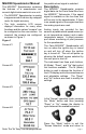
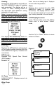
MG2000 Speedometer Manual the paddle wheel signal is selected. The MG2000™ Speedometer combines the features of a speedometer and several digital instruments into one unit: Description • The MG2000™ Speedometer is analog in appearance but is driven by a stepper motor for digital accuracy. • The high resolution LCD screen displays information for many other functions and the various “screens” can be configured as the user wishes. As received, the screens are configured as shown in Figure 1.
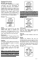
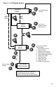
“Normal” mode. If no buttons are pushed for 4 seconds the current screen will stay selected and the unit will return to “Normal” mode (see Figure 2 & 3). turned on, the unit enters a “Self Test” mode. The screen will display “The Self Test Mode Is In Operation” for 10 seconds. The warning lights and back lights will flash. When this is complete, the user selected “Default” screen will appear. From the “Normal” mode, press the “Mode” and “Up” buttons to change to the “Edit” menu (see Figure 3).
Displayed Functions MG2000™ Speedometer The MG2000™ Speedometer is a digital instrument with the appearance of an analog instrument. The MG2000™ Speedometer receives it’s input from a paddle wheel speed sensor OR a pitot pressure input. The “Edit” mode allows selection of the paddle wheel or pitot inputs, calibration of the speedometer. A microprocessor controlled stepper motor moves the pointer to display speed.
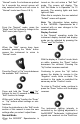
Heading Displays the GPS heading received from the GPS NMEA0183 signal (if installed and connected). The display will be in “TRUE” or “MAG” heading based on the “SET GPS COG DISPLAY” setting selected in the edit mode. Note: If magnetic bearing is not available from the GPS unit, the operator will be unable to select “MAG” in the “set GPS COG display” function.
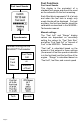
Figure 3 - LCD Display Screens Normal Mode 40 sec. Auto Return or 4 sec. Auto Return Select Mode Edit Mode and 2 sec. Use to change settings. Increase/decrease contrast or or or Use to move between screens. (See Figure 2) Use to move between Edit Functions. 1. 2. 3. 4. 5. 6. 7. 8. 9. 10.
Fuel Functions Fuel Level Sender Fuel Level Sender This display is the equivalent of a standard fuel gauge and should be used as the reference for the fuel remaining. Each filled block represents 1/8 of a tank and when the fuel tank is empty only empty blocks will be displayed. For best accuracy, the fuel level sender should be calibrated as described in the MG2000™ Tachometer manual.
COG (Course Over Ground) If deviation information is not available from the connected GPS, the COG display will default to the display shown at left. This is the normal display with COG indicated as it would be displayed on a compass. If desired, True North data can be displayed by selecting it in the “set GPS COG display” in the edit mode. If deviation information is available from the GPS, the COG display can be selected to display the screen shown at left.
Edit Mode The “Edit” mode is used to adjust or set the values of functions and options in the MG2000 Speedometer. The procedure below specifies the steps to be taken in the “Edit” mode to adjust / set each option. To enter “Edit” mode, press “Mode” and “Up” button while in “Normal” mode To return to “Normal” mode, press “Mode” button once while in “Edit” mode Functions that are set or adjusted in the “Edit” mode 1. 2. 3. 4. 5. 6. 7. 8. 9. 10.
Press and hold the “Up” and “Down” for 2 seconds to reset “Trip Log” to zero (0). Automatically resets trip log to zero and returns to “Edit mode.” Press “Up” or “Down” to select another function or “Mode” to return to “Normal” mode. Organize User Screens 1 2 3 Organize User Screens 1 2 3 Set up Screen 1 1 Screen 1 2 Line 1 3 Item XX 1 Screen 1 2 Line 2 3 Item XX 1 Screen 1 Press and hold the “Up” and “Down” for 2 seconds to select “Organize User Screens.
Press “Up” or “Down” to select another function or “Mode” to return to “Normal” mode. Speedometer Calibration 1 Speedometer 2 Calibration 3 Press and hold the “Up” and “Down” for 2 seconds to select “Speedometer Calibration.” Press “Up” or “Down” to select another function or “Mode” to return to “Normal” mode. NOTE: To calibrate the speedometer another “reference” must be available. This can be the GPS speed (SOG), a radar gun, or some other source of accurate speed indication.
Adjust Clock Offset 1 Set 2 Clock 3 Offset 1 Adjust 2 Clock 3 Offset 1 Set 2 Clock 3 Type 1 Set 2 Clock 3 Type 4 24 Hour Press and hold the “Up” and “Down” for 2 seconds to select “Clock Offset.” Press “Up” or “Down” to select another function or “Mode” to return to “Normal” mode. OR Press “Up” or “Down” while observing clock. When the clock display matches local time , press and hold “Up” and “Down” for 2 seconds to save clock offset and return to “Edit” mode.
Select “Self Test” 1 Select 2 Self 3 Test 1 The 2 Self 3 Test 4 Mode 5 Is in 6 Operation 1 Software Id Press and hold the “Up” and “Down” for 2 seconds to select “Self Test.” Press “Up” or “Down” to select another function. This screen will display for 10 seconds. The backlights will flash three times When “Self Test” is complete the unit will return to the “Edit” mode. Press “Up” or “Down” to select another function or “Mode” to return to “Normal” mode.
Available Functions for Display in MG2000 Speedometer Screens The functions listed below can be displayed in the user configured screens. All of the functions may not be available in your installation. If a function is selected for display and that function does not appear on the screen, the function does not exist in this installation. A function is selected for display by selecting it’s number from the list below. 1. 2. 3. 4. 5. 6. 7. 8. 9. 10. 11.
Notes:
Copyright 2005 by the Thomas G. Faria Corporation, Uncasville CT No part of this publication may be reproduced in any form, in an electronic retrieval system or otherwise, without the prior written permission of the company. Faria® is the trademark of the Thomas G.