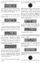
Uncasville, CT INSTRUMENTS F A® RI A .U RP CO 10 A NC LE, CT SVIL MADE IN U. S . 20 A.
Index Description Odometer Trip Odometer Hour-meter Maximum Saved Speed Setting the Speedometer Boot menu Service Hours Service Distance Clear Hours Clear Distance Program High Axle Program Low Axle Input Level control for the speed pulse input Run Menu Clear Odometer Set Speed (Over Speed indicator) Calibrate Hi Axle Calibrate Low Axle Harness P1 6 pin connector Harness P2 4 pin connector Page 1 Page 1 Page 1 Page 1 Page 2 Page 2 Page 2 Page 3 Page 3 Page 4 Page 4 Page 4 Page 4 Page 5 Page 5 Page 5 Page 6
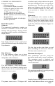
COMMERCIAL SPEEDOMETER Functions available: 1. Odometer display 2. Trip odometer display (resetable) 3. Change the pulses per mile or the pulses per kilometer input. A. PPM adjustment can be done automatically by the microprocessor. B. PPM numbers can be entered using the push-button. C. All features available for both high and low speed axles. Detail description Odometer The commercial speedometer contains an odometer to maintain a record of the total mileage and trip mileage.
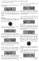
has passed. The interval can be either or both mileage and hours. A seven digit display readout displays the total mileage, the trip mileage, hourmeter or maximum saved speed (cleared by pressing and holding the push-button for 4 seconds while in the maximum speed display), the menu items are scrolled by pressing and releasing the push-button on the speedometer. If a service interval has been passed the display will show a service message (one time only).
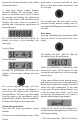
Hours) is used to set the next service interval in hours. When this menu feature is started, the display will show the actual hours when the present hour service interval will occur. The main purpose of this menu feature is to set the next hour service interval time, however it can also be used to check when the present service interval will occur. Starting at the left most digit, the digits will flash on and off for four seconds.
service flag and automatically reset the next hour service. for 32 seconds and the microprocessor will reset itself and will change nothing. The calculation will use the previous interval value. When the operator stops at the “Clr HrS” display and waits four seconds the service interval will be changed.
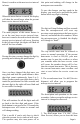
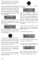
is normally used for magnetic pickups and normal and high for other types. 8. The last menu item “donE” is used to exit from this menu. Leaving the display in “donE” for four seconds will cause the microprocessor to go back to normal operations and change nothing. Run menu Pressing and holding the push-button for two seconds during normal operation will activate the “run menu”. The display will show “HELLO” and wait for you to release the push-button.
of the high axle pulses per mile or kilometer that the speedometer will use to position the pointer and record the correct mileage. This is accomplished by indicating to the speedometer microprocessor, the beginning and end of a measured mile or kilometer. The microprocessor will actually count the pulses that occurred during that mile or kilometer and compute the required parameters. When this mode is activated the speedometer will display “PEndInG “.
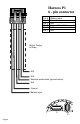
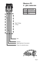
Harness P1 6 - pin connector Pin A Pin B Pin C Pin D Pin E Pin F Battery Input Ground N/A External Push-Button grnd N/A N/A Shrink Tubing or Wrap N/A N/A External push button (ground active) N/A Ground Battery input P1 Page 8 P2
Harness P2 4 - pin connector Pin A Pin B Pin C Pin D Sensor Power Speed Signal Ground N/A Shrink Tubing or Wrap N/A Ground Speed pulses in from sensor Power for external sensor P1 P2 Page 9
Notes: Page 10
Copyright 2005 by the Thomas G. Faria Corporation, Uncasville CT, all rights reserved. No part of this publication may be reproduced in any form, in an electronic retrieval system or otherwise, without the prior written permission of the company.