
Owner manual


To the Owner/Operator/Dealer
All implements with moving parts are potentially hazardous. There is no substitute for a cautious, safe-
minded operator who
recognizes the potential hazards and follows reasonable safety practices. The manu
facturer has designed this implement to be used
with all its safety equipment properly attached, to minimize the chance of accidents.
BEFORE YOU START!! Read the safety messages on the implement and shown in your manual. Observe the rules of safety
and common sense!
Instructions
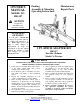
The Model HK-307 hitch adapter kit is designed for
the Allis Chalmers Model CA tractors.
This kit uses the existing hydraulic lift on the tractor
to raise and lower the 3-pt. Hitch.
PACKING
The adapter kit is shi
pped in knocked down condition
so as to command the lowest freight rates. Shipment
consists of 1 cartons and 1 frame assembly.
TRACTOR PREPARATION
Before installing the adapter kit, it is necessary to
remove the existing swinging drawbar assembly.
Check the threaded holes that go into the tractor
housing and make sure the threads are in good condition
and that the holes are clean.
CAUTION! If an air hose is used to blow any
loose rust or dirt from the holes, be sure safety glass
es are
used to prevent particles from entering an eye.
Be sure tires and rims are in good condition. Inflate
tires to the proper recommended air pressure.
Check the tractor’s hydraulic system. Refer to your
tractor operator’s manual or dealer
for any adjustments
necessary to put the hydraulic system in good working
order. (I&T shop manuals will list most specifications
and adjustment instructions –
available from most farm
equipment dealers.)
Check the shield over the PTO stub shaft. Mak
e sure
it is in good condition and bolted securely to the tractor.
Purchase a new shield if old shield is damaged or
missing. (You may have to use a tractor salvage yard for
replacement parts on older tractors.)
It is recommended that a ROPS (Roll-O
ver Protection
Structure) be installed on all tractors. Contact your local
dealer for a ROPS for your tractor.
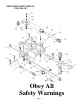
ASSEMBLY
In order to mount this kit, it will first be necessary to
remove the swinging drawbar and mounting brackets
from your tractor. Using the 7/8” x 6-
1/2” draw pin,
attach the main frame to support arm on the underside of
the tractor and secure it with the hairclip pin provided.
Slide the mainframe braces over the outside pins
mounted in the rear axle housings in the position show
n
on the parts drawing and capture them with the hairpins
provided. Pivot the rear of the main frame to the main
frame braces. Tighten these bolts securely.
Pin the pivoting ends of the lift arm leveling
assemblies to the tractor lift brackets wi
th the 5/8” top
link pins and linchpins provided.
On both the outer left-hand and the right-
hand ends
of the hitch main frame, start the ends of the pull pins
(Ref. #5) through the outer pull bracket ears. Position
the pull pin so that the end with NO
hole goes to the
inside.
As soon as the end of the pull pin passes through the
first outer pull bracket ear, slide the pull pin spacer
(Ref #6) on the pin so that it is located between the first
and second pull bracket ears. Slide the pull pin in
further until the end is just entering the second pull
bracket ear.
Then place the forward end of the lift arm between
the large side plate on the main hitch frame and the
second pull bracket. Slide the pull pin in further so that
it goes through the
ball end of the lift arm and enters
the hole in the large side plate.
Rotate the pull pin so that the holes in the pin are
horizontal. Slide the spacer tube and adjust the pull pin
so that a large (5/16”) hairpin clip can be inserted
through the cen
ter hole of the pull pin. This locks the
pull pin in place on each side.
Raise the lift arms, sliding them between the clevis
ends of the lift arm leveling assemblies, and pin them
in place.
Install the stabilizer stub pins (Ref #19) in the
forw
ard holes of each lift arm. Have the large (7/8”)
diameter of the stub pin to the outside of the lift arm
and the threaded nut to the inside.
Do not use a lock
washer under the nut
. Place a screwdriver or small
bar through the linchpin hole and tighten
the nut on the
stub pin.
Place one end of the stabilizer bars (Ref #17) over
the ends of the pull pins on the outer ends of the frame
and secure with linchpins.
The stabilizer bars have threaded ends and can be
adjusted to the correct length by t
urning the center
barrel. Adjust the stabilizer bars, then slide the other
end over the stabilizer stub pins in the lift arms. Secure
in place with linchpins.
NOTE:
When connection the hitch to an implement, it
will be necessary to remove the lift arm
end of the
stabilizer bar from the lift arm. This allows the lift arm
to swing out and be installed on the pull pin of the
Continued on page 2
Page 1