INSTALLATION MANUAL APPLICATION: FA D02 095G (95gph @ 8psi) FA D02 150G (150gph @ 8psi) Cummins 5.
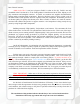
Dear Valued Customer, “Made in the USA” is not just a slogan at FASS; it’s what we live by! FASS is not only assembled in the USA but 98%+ of the FASS product is manufactured in the USA, helping to employ Americans and strengthen America. At FASS, we scrutinize our suppliers and demand the highest quality American-made components. However, this does come at a price, which is one of the main reasons FASS products are more expensive than the competition.
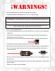
¡WARNINGs! Read all instructions before starting installation of this product! Installing the improper FASS Pump can cause severe engine damage. FASS Recommended Application FA D02 095G Cummins 1989-1993 with stock - moderate horsepower modifications FA D02 150G Cummins 1989-1993 with moderate - extreme horsepower modifications Note: Due to the increase of fuel flow you may encounter a problem with the stock fuel module. Adding a FASS suction tube kit will solve that issue.
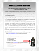
INSTALLATION MANUAL Follow these steps to ensure a simple installation of your new FASS ADJUSTABLE FUEL PUMP 1. Read the installation manual completely before attempting installation. The installation of this product indicates that the buyer has read and understands the limitations of the FASS manufacturers warranty agreement and accepts the responsibility of its terms and conditions. 2. Inventory the package components. Notify the place of purchase immediately of any parts missing or damaged. 3.
Adjustable Fuel Pump Series 95 or 150 GPH 8 PSI (Approximately) A fuel pressure gauge is highly recommended to identify fuel filter life and to prevent engine damage! Adjustment Lock Nut Set screw Boost Compensation Port ‘T’ Fuel Inlet Port “E” To Engine Fuel Pressure Port Installation Step 1: Step 2: Step 3: Step 4: Step 5: Install Electrical Harness Mount Fuel System Install Fuel Line Check/Set Pressure Check Installation
Contents THB-1001 FF-3270 BHB-1001 PFB-2001C MP-9035 FPB-2005 FL-1002 x14’ WH-1002
Mounting Package Contents WE-1001 46044 *Cable Ties* 10-300 PL-1005 DIPF-1003 46260 RS-1002 1/4” Nut 1/4” Lock Washer Ring Terminal QD-1001 1 Hex Bolt 1/2” -20 x 1 1/2” PL-2003 1 1/2” Washers 1/4” washer 1/4” Nut RS-2001 4 1/4 - 20x1.75” 2 1/4 - 20x1.
The installation of the electrical harness is done first, allowing power to be applied to the pump for lubrication purposes later in the installation. A. Using wire stripping tool remove excess insulation off the add-a-fuse and the WH-1005. B. Connect WE-1001 to the WH-1002. Place wire from 46044 and WE-1001 into butt connector. Using crimping tool connect 46044 and WE-1001 with butt connector. Install 46260 to 46044 bottom slot (opening that is near the spade).
E. If fuse panel is located in the cab it will be necessary to guide the single red wire from the relay through the fire wall grommet to access the fuse panel. F. Locate fuse box under hood and select ignition hot fuse. Remove fuse and put Add-A-Fuse in place. Install fuse previously removed. The use of a corrosion preventative on electrical connections is recommended. G. Route WH-1002 wire harness along frame rail to mounting location of pump.
A. . Insert PFB-2002C in to bed channel align the nut with the opening on the channel. B. Secure PFB-2002 and RS-2001 with (1) hex bolt 1/2” -20 x 1 1/2” and (1) 1/2” washer to FPB-2005 C. Secure THB-1001 to bolt on bracket with the RS-1002 and the (5)-1/4-20x1 bolts, 1/4 washers, and 1/4 nuts. With the (4)-1/4-20x 1.75” bolts thread the BHB-10001 to the THB-1001. Note: Use of Anti-seize compound is highly recommended.
D. Using thread tape, install the 2 10-300 into the “T” & “E” ports. Torque to 40 ft./lbs. Connect the male end of the wire harness to the female electrical connector on the FASS pump. Reconnect the battery. Turn key to the “On” position. With the FASS pump on, squirt a liberal amount of WD-40 or other lubricant into the “T” port. This procedure will “wet” the Gerotor and allow for better suction during initial priming. Note: Do Not Put Thread Tape on Flare of Fitting E.
Do Not use sealant on AN (male flare) fittings. Only use sealant on threads installed into pump assembly. A. Using a 3/8” hose clamp install the QD-1001 into the opposite end of the fuel line addressed in the previous step. Oil o-rings inside Quick Disconnect. B. Disconnect factory suction line clip by pressing in on the two tabs located on either side in the connection fitting. Once removed, clean the suction tube and connect the QD-1001 addressed in the previous step. Bed is removed for photo clarity.
F. Disconnect factory fuel line from inlet side of the filter housing and install the DIPF-1003 fuel fitting. Torque to 18 ft/lbs. The factory fuel line can be discarded. See note at bottom of page. G. Cut fuel line and attach PL-2003 90° fitting. Use oil on fitting and hose. H. Attach PL-2003 to DIPF-1003 on the filter housing. Torque to 18 ft/ lbs. Note: Secure all fuel lines with cable ties.
The preset pressure is approximately 8 psi. Follow these steps to check or reset the fuel pressure. The port with 1/8” Allen plug marked with the letter “P” is your fuel pressure port. Exceeding factory fuel pressure may result in severe engine damage. Consult with engine manufacture before adjusting pressure! With the pump running – Loosen the lock nut Turn the adjustment screw clock wise to increase pressure and counter clock wise to decrease pressure.
Disclaimer: To help insure you receive the proper system and customer support at the local level, FASS has a VIP and Authorized Dealer network representing FASS products. This is one reason you must purchase through a dealer to comply with our warranty policies. If you do not, there is no warranty! We recommend you go to www.FASSride.com, click “Find a Dealer”, put in their ZIP code, select the type of dealer, and see if the company you purchased from is listed.