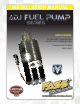
INSTALLATION MANUAL APPLICATION: FA D08 095G (95gph @16psi) FA D08 150G (150gph @ 16psi) Cummins 5.9L 24 Valve 1998.
Dear Valued Customer, “Made in the USA” is not just a slogan at FASS; it’s what we live by! FASS is not only assembled in the USA but 98%+ of the FASS product is manufactured in the USA, helping to employ Americans and strengthen America. At FASS, we scrutinize our suppliers and demand the highest quality American-made components. However, this does come at a price, which is one of the main reasons FASS products are more expensive than the competition.
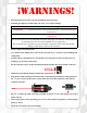
¡WARNINGs! Read all instructions before starting installation of this product! Installing the improper FASS Pump can cause severe engine damage. FASS Recommended Application FA D08 095G Cummins(24 Valve) 1998.5-2004 with stock - moderate horsepower modifications FA D08 150G Cummins (24 Valve) 1998.
INSTALLATION MANUAL Follow these steps to ensure a simple installation of your new FASS ADJUSTABLE FUEL PUMP 1. Read the installation manual completely before attempting installation. The installation of this product indicates that the buyer has read and understands the limitations of the FASS manufacturers warranty agreement and accepts the responsibility of its terms and conditions. 2. Inventory the package components. Notify the place of purchase immediately of any parts missing or damaged. 3.
Adjustable Fuel Pump Series 95 or 150 GPH 16 PSI (Approximately) A fuel pressure gauge is highly recommended to identify fuel filter life and to prevent engine damage! Adjustment Lock Nut Set screw Boost Compensation Port ‘T’ Fuel Inlet Port “E” To Engine Fuel Pressure Port Installation Step 1: Step 2: Step 3: Step 4: Step 5: Install Electrical Harness Mount Fuel Pump Install Fuel Line Check/Set Pressure Review Installation
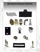
Contents THB-1001 FF-3248 BHB-1001 MP-9009 FPB-2005 WH-1002 FL-1002 x14’
Mounting Package Contents *Cable Ties* FP-1001 10-300 PL-1005 DIPF-1003 PL-2003 QD-1001 HC-1001 Ring Terminal RS-1002 1/4” Lock washer 1/4” Nut 4 1/4 - 20x1.75” 2 1/4 - 20x1.
The installation of the electrical harness is done first, allowing power to be applied to the pump for lubrication purposes later in the installation. A. Using ring terminals, attach red wire of the WH-1002 to the positive battery terminal. Attach green wire to a clean ground, preferably the negative battery terminal. Secure fuse block in a location protected from outside elements. Use of corrosion preventative spray is recommended. B. Disconnect power source to the factory lift pump. 1998.
A. Locate bed bolt and remove the bolt. Position RS-2001 between FPB-2005 and truck bed. B. Secure THB-1001 to bolt on bracket with the RS 1002 and the (2)– 1/4-20x1 bolts, 1/4 washers, and 1/4 nuts. With the (4)-1/4-20x1.75” bolts thread the BHB-1001 to the THB-1001. Note: Use of Anti-seize compound is highly recommended. C. Using thread tape, install the 2 10-300 into the “T” & “E” ports. Torque to 40 ft./lbs.
D. Slid the FASS pump into mounting brackets with the weep hole facing down. Torque (4) bolts to 110 inch pounds. VERY IMPORTANT: REMEMBERING THE POSITION OF THE “T” PORT, THERE IS A SMALL WEEP HOLE IN THE BASE DIRECTLY NEXT TO THE ELECTRIC MOTOR, THIS HOLE MUST AIM DIRECTLY TO THE GROUND!! IMPROPER INSTALLATION OF THE PUMP CAN CAUSE PREMATURE WEAR AND VOID MANUFACTURES WARRANTY.
Do Not use sealant on AN (male flare) fittings. Only use sealant on threads installed into pump assembly. A. Using a 3/8” hose clamp install the fuel line over the knurled flare on the QD-1001. Oil O-rings inside Quick Disconnect. B. Disconnect factory suction line clip by pressing in on the two tabs located on either side in the connection fitting. Once removed, clean the suction tube and connect the QD-1001 addressed in the previous step. Bed is removed for photo clarity.
G. Route the fuel line to the inlet port of the factory filter housing. Refer to your vehicles application: Note: If the truck has had the retrofitted in-tank pump installed, usually installed by a Dodge Dealer after a fuel lift pump failure, a separate suction tube will need to be installed in the fuel tank. This retrofit will not allow fuel to be drawn through the FASS pump! Order a STK (Suction Tube Kit) from FASS. H.
These models can have the inlet fitting on top of the filter canister or on the side. E. Disconnect inlet fuel line to the filter housing. Install DIPF-2003. Torque to 18 ft/lbs. F. Measure and cut fuel line. Insert PL-2003 90° Push-Lok fitting using oil. Install fitting to DIPF-2003. Torque to 18 ft/lbs. Note: Secure all fuel lines with cable ties. Cable ties are an economical way to prevent the possibility of problems occurring! E.
The preset pressure is approximately 16 psi. Follow these steps to check or reset the fuel pressure. The port with 1/8” Allen plug marked with the letter “P” is your fuel pressure port. Exceeding factory fuel pressure may result in severe engine damage. Consult with engine manufacture before adjusting pressure! With the pump running – Loosen the lock nut Turn the adjustment screw clock wise to increase pressure and counter clock wise to decrease pressure.
Answer the following questions: Did the vehicle start fine without the FASS or HPFP? Do you have high mileage on the VP44? If yes, have your VP44 checked.
Disclaimer: To help insure you receive the proper system and customer support at the local level, FASS has a VIP and Authorized Dealer network representing FASS products. This is one reason you must purchase through a dealer to comply with our warranty policies. If you do not, there is no warranty! We recommend you go to www.FASSride.com, click “Find a Dealer”, put in their ZIP code, select the type of dealer, and see if the company you purchased from is listed.