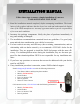
INSTALLATION MANUAL APPLICATION: FA D10 125G (125gph @ 45psi) Cummins 5.
Dear Valued Customer, “Made in the USA” is not just a slogan at FASS; it’s what we live by! FASS is not only assembled in the USA but 98%+ of the FASS product is manufactured in the USA, helping to employ Americans and strengthen America. At FASS, we scrutinize our suppliers and demand the highest quality American-made components. However, this does come at a price, which is one of the main reasons FASS products are more expensive than the competition.
¡WARNINGS! Read all instructions before starting installation of this product! Installing the improper FASS Pump can cause severe engine damage. FASS FA D10 125G Recommended Application Cummins (12 Valve) 1994-1998 with stock - moderate horsepower modifications Note: Due to the increase of fuel flow you may encounter a problem with the stock fuel module. Adding a FASS suction tube kit will solve that issue. Secure vehicle from ROLLING! Use caution when drilling.
INSTALLATION MANUAL Follow these steps to ensure a simple installation of your new FASS ADJUSTABLE FUEL PUMP 1. Read the installation manual completely before attempting installation. The installation of this product indicates that the buyer has read and understands the limitations of the FASS manufacturers warranty agreement and accepts the responsibility of its terms and conditions. 2. Inventory the package components. Notify the place of purchase immediately of any parts missing or damaged. 3.
Adjustable Fuel Pump Series 125 GPH 45 PSI (Approximately) A fuel pressure gauge is highly recommended to identify fuel filter life and to prevent engine damage! Adjustment Lock Nut Set screw Boost Compensation Port ‘T’ Fuel Inlet Port “E” To Engine Fuel Pressure Port InstallaStep 1: Step 2: Step 3: Step 4: Step 5: Install Electrical Harness Mount Fuel System Install Fuel Line Check/Set Pressure Check Installation
Contents THB-1001 FF-3248 BHB-1001 MP-9037 FPB-2005 WH-1005 FL-1002 x14’
Mounting Package Contents *Cable Ties* RS-1002 BHF-1002 PL-1005 10-300 PL-1004 1/2” Plug BHN-1001 LW-1001 PL-2003 DIPF-1004 46260 46044 Ring Terminal OR-223 HC-1001 ST-1005Px16” 1/4” washer 1/4” Nut RS-2001 4 1/4 - 20x1.75” 2 1/4 - 20x1.
The installation of the electrical harness is done first, allowing power to be applied to the pump for lubrication purposes later in the installation. A. Using wire stripping tool remove excess insulation off the add-a-fuse and the WE-1001. B. Place wire from 46044 and WE-1001 into butt connector. Using crimping tool connect 46044 and WE1001 with butt connector. Install 46260 to 46044 bottom slot (opening that is near the spade). Route Add-a-fuse lead through the fire wall using existing grommet.
E. If fuse panel is located in the cab it will be necessary to guide the single red wire from the relay through the fire wall grommet to access the fuse panel. F. Locate fuse box under hood and select ignition hot fuse. Remove fuse and put Add-A-Fuse in place. Install fuse previously removed. The use of a corrosion preventative on electrical connections is recommended. G. Route WH-1005 wire harness along frame rail to mounting location of pump.
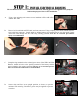
Some of the photo’s are of a different application, procedures are the same. A. Very Important: Before removing the fuel tank, identify “ALL” areas of clearance between the tank and bed to install the draw tube assembly. The closer the suction tube is placed to the center of the fuel tank, front to back and left to right, the more usable fuel there will be! B. Remove the filler neck and overflow tubes from the truck by loosening the clamps at both ends. C.
I. Before drilling marked location, clean area of debris. Using the photo, double check area selected for any interference including the fuel level J. Drill a 1 3/8” hole, catching all debris. De-bur hole and remove any missed debris in the fuel tank. K. VERY IMPORTANT: Support fuel tank on both ends allowing the natural formation of the tank to take place. Failure to perform this step can and will create an issue with less usable fuel! L.
O. Route fuel line over the frame rail while reinstalling the fuel tank. Torque tank hanger bolts to proper specifications. P. Connect factory wire harness to the fuel module along with the factory fuel lines. FASS harness Q. Reattach filler neck and clamps.
A. Locate bed bolt and remove the bolt. Position RS-2001 between FPB-2005 and truck bed. B. Secure THB-1001 to bolt on bracket with the RS 1002 and the (2)– 1/4-20x1 bolts, 1/4 washers, and 1/4 nuts. With the (4)-1/4-20x1.75” bolts thread the BHB-1001 to the THB-1001. Note: Use of Anti-seize compound is highly recommended. C. Using thread tape, install the 2 10-300 into the “T” & “E” ports. Torque to 40 ft./lbs.
D. Slid the FASS pump into mounting brackets with the weep hole facing down. Torque (4) bolts to 110 inch pounds. VERY IMPORTANT: REMEMBERING THE POSITION OF THE “T” PORT, THERE IS A SMALL WEEP HOLE IN THE BASE DIRECTLY NEXT TO THE ELECTRIC MOTOR, THIS HOLE MUST AIM DIRECTLY TO THE GROUND!! IMPROPER INSTALLATION OF THE PUMP CAN CAUSE PREMATURE WEAR AND VOID MANUFACTURES WARRANTY.
Do Not use sealant on AN (male flare) fittings. Only use sealant on threads installed into pump assembly. A. Route fuel line to the suction port on the FASS pump labeled “T”. Cut the fuel line. Insert PL-1005 into fuel line using oil. Attach to 10-300 in ‘T’ port. Torque to 18 ft./lbs. B. Install in-line fuel filter in an accessible location in the suction line using the HC-1001’s. Make sure the fuel flows in the direction of the arrow on the canister.
F. Attach the PL-2003 to DIPF-1003. Torque to 18 ft./lbs. G. Remove banjo bolt connecting the outlet line of the factory fuel filter. This is the line in front of the inlet line removed in step f. H. Move the injector return line from step f and stack on top of the outlet line of the factory fuel filter. Light bending will be required, be very careful not to kink or crack this fuel line. Install the Banjo Bolt removed in step f. Torque to 18 ft./lbs. Note: Secure all fuel lines with cable ties.
The preset pressure is approximately 45 psi. Follow these steps to check or reset the fuel pressure. The port with 1/8” Allen plug marked with the letter “P” is your fuel pressure port. Exceeding factory fuel pressure may result in severe engine damage. Consult with engine manufacture before adjusting pressure! With the pump running – Loosen the lock nut Turn the adjustment screw clock wise to increase pressure and counter clock wise to decrease pressure.
Disclaimer: To help insure you receive the proper system and customer support at the local level, FASS has a VIP and Authorized Dealer network representing FASS products. This is one reason you must purchase through a dealer to comply with our warranty policies. If you do not, there is no warranty! We recommend you go to www.FASSride.com, click “Find a Dealer”, put in their ZIP code, select the type of dealer, and see if the company you purchased from is listed.