INSTALLATION MANUAL APPLICATION: FA F16 095G (95gph @ 8psi) FA F16 150G (150gph @ 8psi) Ford Powerstroke 6.
Dear Valued Customer, “Made in the USA” is not just a slogan at FASS; it’s what we live by! FASS is not only assembled in the USA but 98%+ of the FASS product is manufactured in the USA, helping to employ Americans and strengthen America. At FASS, we scrutinize our suppliers and demand the highest quality American-made components. However, this does come at a price, which is one of the main reasons FASS products are more expensive than the competition.
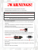
¡WARNINGs! Read all instructions before starting installation of this product! Installing the improper FASS Pump can cause severe engine damage. FASS Recommended Application FA F16 095G Powerstroke (6.4L) 2008-2010 with stock - moderate horsepower modifications FA F16 150G Powerstroke (6.4L) 2008-2010 with moderate - extreme horsepower modifications Note: Due to the increase of fuel flow you may encounter a problem with the stock fuel module.
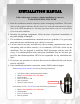
INSTALLATION MANUAL Follow these steps to ensure a simple installation of your new FASS ADJUSTABLE FUEL PUMP 1. Read the installation manual completely before attempting installation. The installation of this product indicates that the buyer has read and understands the limitations of the FASS manufacturers warranty agreement and accepts the responsibility of its terms and conditions. 2. Inventory the package components. Notify the place of purchase immediately of any parts missing or damaged. 3.
Adjustable Fuel Pump Series 95 or 150 GPH 8 PSI (Approximately) A fuel pressure gauge is highly recommended to identify fuel filter life and to prevent engine damage! Adjustment Lock Nut Set screw Boost Compensation Port ‘T’ Fuel Inlet Port “E” To Engine Fuel Pressure Port Installation Step 1: Step 2: Step 3: Step 4: Step 5: Install Electrical Harness Mount Fuel System Install Fuel Line Check/Set Pressure Check Installation
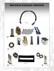
Contents THB-1001 FF-3248 BHB-1001 PFB-2001C MP-9013 FPB-2005 WH-1002 FL-1002 x9’
Mounting Package Contents WE-1006 10-300 Wire Ties PLB-1238 1 Hex Bolt 1/2” -20 x 1 1/2” Ring Terminal 1 PL-1005 QD-1002 PLB-1212 HC-1001 1/2” Washers 1/4” washer 1/4” Nut RS-2001 4 1/4 - 20x1.75” 2 1/4 - 20x1.
The installation of the electrical harness is done first, allowing power to be applied to the pump for lubrication purposes later in the installation. A. Using ring terminals, attach red wire of the WH-1004 to the positive battery terminal. Attach green wire to a clean ground, preferably the negative battery terminal. Secure fuse block in a location protected from outside elements. The use of corrosion preventative spray is recommended. B.
Some of the photo’s are of a different application, procedures are the same. A. Insert PFB-2001C in to bed channel align the nut with the opening on the channel. . B. Secure PFB-2002 and RS-2001 with (1) hex bolt 1/2” -20 x 1 1/2” and (1) 1/2” washer to FPB-2005 C. Secure THB-1001 to bolt on bracket with the RS-1002 and the (5)-1/4-20x1 bolts, 1/4 washers, and 1/4 nuts. With the (4)-1/4-20x 1.75” bolts thread the BHB-10001 to the THB-1001. Note: Use of Anti-seize compound is highly recommended.
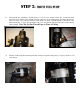
D. Using thread tape, install the 2 10-300 into the “T” & “E” ports. Torque to 40 ft./lbs. Connect the male end of the wire harness to the female electrical connector on the FASS pump. Reconnect the battery. Turn key to the “On” position. With the FASS pump on, squirt a liberal amount of WD-40 or other lubricant into the “T” port. This procedure will “wet” the Gerotor and allow for better suction during initial priming. Note: Do Not Put Thread Tape on Flare of Fitting E.
VERY IMPORTANT: REMEMBERING THE POSITION OF THE “T” PORT, THERE IS A SMALL WEEP HOLE IN THE BASE DIRECTLY NEXT TO THE ELECTRIC MOTOR, THIS HOLE MUST AIM DIRECTLY TO THE GROUND!! IMPROPER INSTALLATION OF THE PUMP CAN CAUSE PREMATURE WEAR AND VOID MANUFACTURES WARRANTY. F. Disconnect the factory power plug to the HFCM lift pump. Clean plug and install the WE-1006 extension connector. Plug female plug of the WH-1002 harness into pump. Reconnect the battery. Turn key on.
Do Not use sealant on AN (male flare) fittings. Only use sealant on threads installed into pump assembly. A. Disconnect factory suction line and clip by pressing in on the two tabs located on either side on the connecting fitting. Thoroughly clean this suction port . Helpful Hints: If more space is required to access the top of the fuel tank, loosen the strap nuts to the end of the stud. This will gain you about 3” more working room. B. Insert QD-1002 and clamp into opposite end of fuel line.
F. Using quick disconnect tools, remove the fuel lines from the front of the factory HFCM lift pump. Remove the fuel lines attached to the rear of the factory HFCM lift pump by pressing in on the tabs. G. Route the fuel line from the “E” port of the FASS to the factory lift pump’s outlet quick disconnect and cut to length. Insert the PLB1212 into FASS fuel line using oil. Slide the PLB-1212 into the factory quick disconnect until you hear a click. Lock down factory retainer clip. H.
The preset pressure is approximately 8 psi. Follow these steps to check or reset the fuel pressure. The port with 1/8” Allen plug marked with the letter “P” is your fuel pressure port. Exceeding factory fuel pressure may result in severe engine damage. Consult with engine manufacture before adjusting pressure! With the pump running – Loosen the lock nut Turn the adjustment screw clock wise to increase pressure and counter clock wise to decrease pressure.
Disclaimer: To help insure you receive the proper system and customer support at the local level, FASS has a VIP and Authorized Dealer network representing FASS products. This is one reason you must purchase through a dealer to comply with our warranty policies. If you do not, there is no warranty! We recommend you go to www.FASSride.com, click “Find a Dealer”, put in their ZIP code, select the type of dealer, and see if the company you purchased from is listed.