
Install Instructions

Page 1 of 4 www.fast-stat.com
Model 1000
Installation Instructions
● The Model 1000 provides an additional control wire
between a thermostat and indoor unit, or indoor unit
and outdoor unit.
● Compatible with all 24VAC heating and cooling
systems.
● Can provide a common connection ‘C’ using a
thermostat cable with 3 or more wires. For adding
a common with only 2 wires see the FAST-STAT
Common Maker.
1. Measure the transformer voltage to ensure it is
between 23-28VAC. If it is outside this range the
Model 1000 may not work as intended.
2. Smart thermostats may not automatically detect
the connected equipment when using a Model 1000.
These connections must be manually configured in
the thermostat’s settings.
3. Jumper the Receiver’s purple wire to transformer ‘R’.
Both relays in the Receiver should energize, outputting
24VAC on the Receiver’s green and yellow wires. If the
relays won’t energize from this test, then the Receiver
may be faulty.
4. At the thermostat, jumper the thermostat wire
connected to the Receiver’s purple wire to thermostat
‘R’. This should energize both relays in the Receiver
and output 24VAC on the Receiver’s green and
yellow wires. If the relays do not energize, there is an
problem with the connection between the Sender’s
and Receiver’s purple wires.
5. Jumper the Sender’s green wire to thermostat ‘R’. This
should output 24VAC on the Receiver’s green wire.
Repeat the test with the yellow wire. If the output
wires do not measure 24VAC when activated, there is
a problem with the Sender. If this test was successful
then there is a problem with the thermostat.
● This product should only be installed by a qualified
technician.
● Requires a Class 2 transformer providing 23-28VAC.
● The total connected load must not exceed 2 amps.
● The connected load cannot operate at more than
30VAC (not designed for direct connection to 120VAC
equipment).
● To avoid risk of electrical shock or equipment damage,
disconnect power before beginning installation.
The Sender is the smaller component and has purple,
yellow, and green wires. It is installed in the wall behind
the thermostat.
The Receiver is the larger component and has red, black,
purple, yellow, and green wires. It is typically installed in
the indoor unit cabinet, or a location without exposure to
liquids or high temperatures.
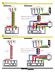
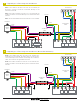
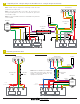
Find the relevant wiring diagram for the system (pages
2-4) and connect the wires accordingly.
If extending the wiring between an indoor and outdoor
unit, the Sender can be placed inside the indoor unit
cabinet or grouped with other wiring.
● Remove the thermostat from the wall.
● Place the Sender in the wall and connect the wires to
the sub-base according to the relevant wiring diagram
(pages 2-4) for the system. The Sender will hang by its
wires and does not require any mounting.
● Place the thermostat back on the wall.
Overview
Testing
Troubleshooting
Internal Wiring
Contact Us
Electrical Safety
Sender Installation
Receiver Installation
After the Model 1000 has been installed, check each
control to ensure it is working correctly:
If the Model 1000 does not work as intended, proceed
to Troubleshooting to check for manufacturing defects,
installation errors, and other issues.
1. Use the thermostat to activate the equipment on the
green wire and check that it turns on and off correctly.
2. Use the thermostat to activate the equipment on the
yellow wire and check that it turns on and off correctly.
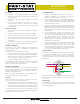
The Receiver’s green and yellow wires are each connected
to a relay. One side of the relay is connected to transformer
‘R’ through the red wire. When a relay is energized, it
connects transformer ‘R’ to the respective green or yellow
output wire.
For installation assistance, our technical support line can
be reached at 1-800-775-4750, 9am-5pm PST, or emailed
at info@nordictech.ca
The power for the relay coils travels through the purple and
black wires. The load side of the relays is not connected to
the coil side.
R
To Sender
RELAYS
Y
G
C