
Install Instructions

Page 1 of 4 www.fast-stat.com
Model 7000
Installation Instructions
● For air conditioner to heat pump conversions. Extends
the wiring between a thermostat, indoor unit, and
heat pump.
● Provides R, C, G, Y1, Y2, W, and O/B over the 4-wire
thermostat cable, and Y1, Y2, O/B, and W over the
2-wire condenser cable.
● If the thermostat cable does not require more wires,
a Model 9000 can be used to extend only the wiring
from the indoor unit to heat pump.
● This product should only be installed by a qualified
technician.
● Requires a Class 2 transformer providing 23-38VAC.
● The total connected load cannot exceed 2 amps.
● The connected load cannot operate at more than
30VAC (not designed for direct connection to 120VAC
equipment).
● To avoid risk of electrical shock or equipment damage,
disconnect power before beginning installation.
The Sender is the smaller component and is installed inside
the wall behind the thermostat.
The Indoor Unit Module is installed inside the cabinet of
the air handler or furnace. If there is not enough space
inside the cabinet, it may be located in any dry location
without exposure to high temperatures or water.
The Heat Pump Module is installed inside the cabinet of the
heat pump. It is not rated for direct exposure to outdoor
conditions, and should not be installed outside of the heat
pump cabinet.
Note: The Sender will produce a small amount of heat
while operating. Keep the Sender wires as long as possible
to maximize the distance between the Sender and
thermostat. Do not install the Sender in insulated walls.
● If the hole where the thermostat cable wires come
through is not big enough to fit the Sender, enlarge it.
● Place the Sender in the wall and connect the wires
to the sub-base according the wiring diagram (pages
3-4). The Sender will hang by its wires and does not
require any mounting.
● Place the thermostat back on the sub-base.
Overview
Single-Stage Heat Pump
Electrical Safety
Sender Installation
Module Installation
For single-stage heat pumps, connect the Sender’s brown
wire to thermostat ‘Y’ instead of the Sender’s yellow wire.
The Sender’s yellow wire should be taped back as it will
not be used.
The Heat Pump Module’s yellow and brown wires should
both connect to the heat pump’s ‘Y’ terminal.
If the indoor unit’s fan only has one speed, the Indoor Unit
Module’s brown wire should be taped back as it will not
be used.
If the indoor unit requires an O/B connection, the blue wire
from the Indoor Unit Module is used. Otherwise, the blue
wire should be taped back as it will not be used.
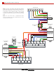
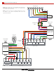
There are two installation methods, ‘Grounded Commons’
and ‘Two Transformers’.
Grounded Commons requires a black wire from both
the Indoor Unit Module and Heat Pump Module to be
grounded (page 3).
Two Transformers requires an external 240:24V transformer
to be installed at the location of the heat pump. It does not
require the use of earth ground (page 4).
Single-Stage Fan
Indoor Unit Reversing Valve
Installation Methods
Two Transformer Test
The Two Transformer test ensures that the transformers
in the system are connected in parallel. It is only required
if using the ‘Two Transformer’ wiring method. The
transformer wiring affects the system when the heat pump
is in defrost mode, which should activate the indoor unit’s
heating system.
If the transformers are not in parallel (and are in series
instead), the defrost mode will trip a resettable fuse inside
the Heat Pump Module, and the indoor unit’s heating
system will not start. Reversing the leads on the secondary
side of the heat pump’s 24V transformer will fix the issue.
No damage will occur when the resettable fuse is tripped.
The resettable fuse takes approximately 30 seconds to
reset after being tripped, and must be reset for the defrost
mode to work.
At the Thermostat
At the Heat Pump
1. Set the thermostat so that the heat pump is running in
heating mode. For 2-stage heat pumps the compressor
must be running in high speed.
2. Manually set the heat pump to ‘Defrost Mode’ (see
heat pump manual for instructions)
3. Check if the indoor unit’s heating system is on. If it is,
the test is complete and no further steps are required.
If it is not, proceed to step 4.
4. Switch the secondary leads of the 24V transformer
powering the heat pump and Heat Pump Module.
The transformer lead previously connecting to ‘R’ will
instead connect to ‘C’. The transformer lead previously
connecting to ‘C’ will instead connect to ‘R’.