
Installation Guide


Table Of Contents
- Purpose & Applicability of This Guide
- Special Considerations and Safety Warnings
- Table of Contents
- 1. Introducing Intelligent Backhaul Radio (“IBR”)
- 2. Getting Started
- 3. Communicating with IBR
- 4. Preconfiguring IBRs
- 4.1.1 Web Graphical User Interface (GUI) – User names and passwords for the GUI are managed independently from CLI user names and passwords. For additional information, see the GUI section of the CLI Guide.
- 5. Installing IBR
- 5.3.1 Mounting Location - Choosing the best possible mounting location for IBR is important for safety, security, and link performance.
- 5.3.2 Fastback Networks’ Articulating Bracket - Fastback Networks offers an articulating mount that can be mounted on walls or masts and adjusted up to + 45 degrees in elevation and azimuth in 15 degree increments. The figure below shows the mountin...
- 6. Features & Functionality
- 7. Field Test Procedure
- Federal Communications Commission (FCC) Compliance Statement
IBR Installation Guide
Page 17 of 21 Doc # 770-00033.0
Jan. 22, 2016
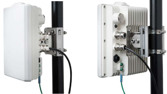
5.4 Power & Ethernet Connections
When IBR has been securely mounted, connect a power source.
Include a secured drip loop for all connections to IBR. The loop will provide some strain relief to the
connectors and prevent water from flowing along the cable to the connector.
If the PoE
+
source is also connected to an Ethernet source, data will flow through IBR’s Ethernet port ge0.
If the power indicator LED does not illuminate when the power connection is made, consider the following:
• Is the RJ-45 connector securely inserted into both the PoE
+
source and IBR?
• Is power applied to the PoE
+
source? Check the indicator lights on the PoE
+
source if applicable.
• Are the cables of the proper type (CAT5E or CAT6)?
• Are the cables in good working order? (Cables should be certified using a Byte Brothers, Fluke, or
similar certifier.)
5.5 Fabricating an Ethernet Cable
The RJ-45 Ethernet connectors on IBR will work with CAT5E and CAT6 cables and other cables having an
outer diameter between 5.0 and 9.0 mm. NOTE: Use only weatherproof, UV-rated, shielded cable.
To install a connector and RJ-45 plug on a shielded cable:
• Strip the cable jacket 12.0 mm.
• Install the RJ-45 plug.
- Untwist the individual strands.
- Insert the cables into the RJ-45 plug in the order shown below.
1. White/orange 5. White/blue
2. Orange 6. Green
3. White/green 7. White/brown
4. Blue 8. Brown
- Wrap the ground wire around the cable jacket underneath the back of the RJ-45 plug.
- Crimp the plug using a crimping tool.
• Install the weatherproof gland pieces on the connector. Note that the rubber O-shaped seal is pre-split
and can be wrapped around the outer RJ-45 jacket.
Additional weatherproof connectors may be obtained from Fastback Networks.
The images below illustrate assembly of the RJ-45 plug.
Figure 11 – RJ-45 Plug Assembly