
Installation Guide


Table Of Contents
- Purpose & Applicability of This Guide
- Special Considerations and Safety Warnings
- Table of Contents
- 1. Introducing Intelligent Backhaul Radio (“IBR”)
- 2. Getting Started
- 3. Communicating with IBR
- 4. Preconfiguring IBRs
- 4.1.1 Web Graphical User Interface (GUI) – User names and passwords for the GUI are managed independently from CLI user names and passwords. For additional information, see the GUI section of the CLI Guide.
- 5. Installing IBR
- 5.3.1 Mounting Location - Choosing the best possible mounting location for IBR is important for safety, security, and link performance.
- 5.3.2 Fastback Networks’ Articulating Bracket - Fastback Networks offers an articulating mount that can be mounted on walls or masts and adjusted up to + 45 degrees in elevation and azimuth in 15 degree increments. The figure below shows the mountin...
- 6. Features & Functionality
- 7. Field Test Procedure
- Federal Communications Commission (FCC) Compliance Statement
IBR Installation Guide
Page 19 of 21 Doc # 770-00033.0
Jan. 22, 2016
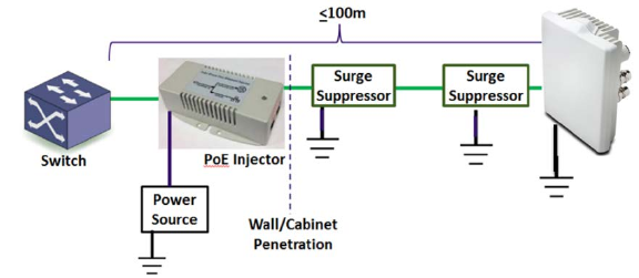
Figure 12 – Surge Suppressors
Surge suppressors should be installed ahead of the cable ingress to the enclosure or structure housing the
switch in order to maximize protection to the switch, and near to IBR to protect IBR. Surge suppressors
should be connected to a true earth ground with materials that meet the manufacturer’s specifications.
5.7 Link Establishment
IBR will automatically select the best combination of channel frequencies and bandwidth for a link.
• Wait for radios to finish booting and establishing a link. Boot time is approximately 3½ minutes and an
additional time of 4 to 10 minutes will be required to establish a link.
If a link is not automatically established within ten minutes, then consider the following troubleshooting
suggestions:
• Check to ensure that the partner IBR on the link is operational.
• Change the direction (azimuth and/or elevation) in which the IBR is pointed.
• Move the IBR’s mounting location up or down to minimize path obstructions.
• Determine if the link is too long or obstructed for the environment.
6. Features & Functionality
6.1 AnyLOS Technology
Fastback’s proprietary AnyLOS technology enables operators to use IBR in difficult RF environments without
worrying about RF tuning. IBR will automatically adjust the following parameters to maximize throughput:
• Channel bandwidth (10, 20, or 40MHz).
• Center frequency.
• Modulation Coding Scheme (MCS) – MCS can be any value from 1–14.
• Transmitter output power - IBR will adjust the transmitter output power automatically to avoid
exceeding emissions requirements. IBR takes output power into account when estimating the
bandwidth available on any given frequency. The frequency vs. output power relationship is shown in
the CLI Guide.
6.2 Communication Protocols
IBR can be managed by an operator using:
• CLI via SSH or Telnet
• GUI via HTTP or HTTPS
• SNMP
6.3 Software Management
• Software upgrades to IBR can be made by an operator.