
Installation Guide

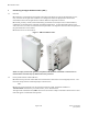
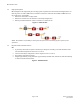
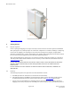
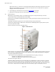
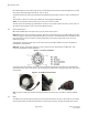
Table Of Contents
- Purpose & Applicability of This Guide
- Special Considerations and Safety Warnings
- Table of Contents
- 1. Introducing Intelligent Backhaul Radio (“IBR”)
- 2. Getting Started
- 3. Communicating with IBR
- 4. Preconfiguring IBRs
- 4.1.1 Web Graphical User Interface (GUI) – User names and passwords for the GUI are managed independently from CLI user names and passwords. For additional information, see the GUI section of the CLI Guide.
- 5. Installing IBR
- 5.3.1 Mounting Location - Choosing the best possible mounting location for IBR is important for safety, security, and link performance.
- 5.3.2 Fastback Networks’ Articulating Bracket - Fastback Networks offers an articulating mount that can be mounted on walls or masts and adjusted up to + 45 degrees in elevation and azimuth in 15 degree increments. The figure below shows the mountin...
- 6. Features & Functionality
- 7. Field Test Procedure
- Federal Communications Commission (FCC) Compliance Statement
IBR Installation Guide
Page 7 of 21 Doc # 770-00033.0
Jan. 22, 2016
1.3 Deployment Options
IBR is designed to be deployed in pairs creating a point-to-point link, as illustrated in the diagram below. In
referring to the two radios, IBR nearest to the fiber connection is called the “donor IBR” and IBR nearest to
the cell site is the “remote IBR”.
• IBR can be connected to an edge switch.
• IBRs can be connected to one another in a multi-hop configuration.
• IBR can provide backhaul for a direct connection to a small cell site.
Figure 2 – Small Cell Site
NOTE: The installer is responsible for ensuring that the system is used exclusively for fixed, point-to-point
operations.
1.4 Physical & Environmental Features
IBR:
• Is passively cooled and can operate continuously at full power and duty cycle under maximum solar
load at ambient temperatures from -40ᵒ
C to +60ᵒ
C.
• Can be stored safely at temperatures in the range from -55ᵒ C to +85ᵒ C.
• Has an IP66 environmental rating.
• Weighs approximately 3.5 kg with and is approximately 200 mm wide, 260 mm tall, and 100 mm deep
as shown in the illustration below.
Figure 3 - IBR Dimensions