
User Manual


FasTest Inc. 1646 Terrace Drive Roseville, MN 55113 Phone: 651-645-6266 Toll Free: 800-444-2373 www.fastestinc.com
Operating Instructions
Note: A tapered washer with a counterbore is used on all FI01, FI1,
FI2, FI3 and FI4 connectors. The retaining ring will be recessed in
the washer’s counterbore when the connector is pressurized
Operating Instructions for FI and FIxM (Metric Termination)
Internal Pneumatic Operated Connector.
FI connectors provide fast, leak-free connections for pressure and vacuum
testing, uid lling and ushing. The connectors are activated by
compressed regulated air acting on a piston which expands an
elastomeric seal to form a leak-tight connection. Testing, lling or ushing
of the piece is accomplished by introducing liquid or gas media through
the FasTest FI connector.
The use of pressurized media for sealing, testing and lling requires a
thorough understanding of the FasTest FI Installation and Operating
Instructions.
Do not operate FasTest connectors without completely reading and
understanding the following Installation and Operating Instructions.
Read and understand each of the following six steps
before operating the connector.
A. Installation of seals.
B. Extended shaft, stroke limit
C. Tapered front washer feature
D. Mounting the connector.
E. Attachment of pilot pressure and test media supply
lines.
F. Connector operation instructions.
A: Installation of Seals
1. For seal replacement, remove retaining ring from shaft tip and slide off
old seal set and washers. Spacer piece is to remain on connector shaft.
2. Seal Set contains elastomer seals, washers and retaining ring. For
complete listing of seal set size ranges see Chart 2.
3. Verify that seals and washers are the same size (outside diameter).
4. Assemble seal set onto shaft per Diagram 1.
5. Attach new retaining ring to groove in shaft tip. Flat side of retaining ring
must face away from washer.
6. A tapered washer with a counterbore is used at the shaft end on
all FI01, FI1, FI2, FI3 and FI4 connectors. The retaining ring will be
contained within the counterbore when pilot pressure is delivered to the
connector
CAUTION:
1) Periodically inspect connector, seals and washers for wear or
damage. Replace worn or damaged connector seal sets to prevent
loss of sealability and personal injury.
2) If replacing seals only, inspect washers for warping, corrosion, or
excessive wear.
3) Replace complete FasTest main seal set if washers are
warped, corroded or worn.
4) Always replace retaining ring when changing the main seal.
B: Extended Shafts:
Connectors with extended shafts are
designed for sealing remote ports or for
applications requiring connectors to be
offset rather than side-by-side mounted
which may be required when multiple test
ports have close center-to-center distances.
Stroke Limiters:
FI connectors that have shaft extensions of at least one inch (1”) beyond
the standard for any model FI connector will be assembled with a stroke
limiter. This feature will prevent over pressurization and excessive travel
of the FI seals when pilot pressure is applied to an FI not placed in a test
piece.
Additionally, if an FI stroke limiter prevents sufcient pressurization for
a sealing or testing application, it may be removed very easily without
reducing the effectiveness of the connector.
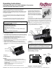
C: Dimensions
Retaining Ring
Flat Washer
Seal(s)
Flat Washer
Stroke Limiter
Standard on 1” or longer extended FI shafts
Spacer, Extended
Spacer,
Nominal
Housing
Piston
Spacer
Retaining Ring
Tapered Washer
Flat Washer
Seal(s)
Diagram 1:
FI1 with Seal Set
Diagram 2:
FI5 1” extended shaft and standard seal set
Maximum Test Pressure: 120 psi
Vacuum Rating: 10-8 torr
A
F
K
D
E
C
Test
Port
Mounting
Holes
Pilot
Port
Diagram 3: Connector Features
L
WP008 1/2009 rev. C