
Information
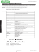


L – Value (rated inductance)
≥ 1 MHz measured with HP 4286A RF LCR meter at frequency f
L
< 1 MHz measured with HP 4194A RF LCR meter at frequency f
L
Q – Factor (min)
≥ 1 MHz measured with HP 4287A RF LCR meter at frequency f
Q
< 1 MHz measured with HP 4194A RF LCR meter at frequency f
Q
SRF (min)
Measured with HP 8753ES Network Analyzer
DCR (max)
Measured at 25°C
Operating Temperature
For ceramic core from -40°C to +150°C (Includes component self-heating)
For ferrite core from -40°C to +85°C
Surface Finishing
Epoxy molded flat top for perfect pick and place assembly
Pad Metallization
Gold flash as top layer
Wire Termination
Spot welding
Recommended soldering method
Reflow
Moisture Sensitivity Levels (MSL)
MSL Level 1, indicating unlimited floor life at ≤ 30°C / 85% relative humidity
Solderability
Using lead free solder (Sn 99.9) at 260°C ± 5°C for 5 ± 0.5 seconds, min 90% solder coverage
of metallization
Standard: IEC 68-2-20 (Ta)
Resistance to Soldering Heat
Resistant to 260°C ± 5°C for 10 ± 1 seconds
Standard: IEC 68-2-20 (Tb)
Resistance to Solvent
Resistant to Isopropyl alcohol for 5 ± 0.5 minutes at 23°C ± 5°C
Standard: IEC 68-2-45
Climatic Test
Defined by the following standards
IEC 68-2-1 for Cold test: -55°C for 96 hours
IEC 68-2-2 for Dry heat test: +85°C for ferrite core and 125°C for ceramic core for 96 hours
IEC 60068-2-78 for Humidity test: 40°C at RH 95% for 4 days
Thermal Shock Test
Temperature cycle (ceramic) : -40°C to +125°C to -40°C
Temperature cycle (ferrite) : -40°C to +85°C to -40°C
Max/Min temperature duration: 15 minutes
Temperature transition duration: 5 minutes
Cycles: 25
Standard: MIL-STD-202G
Adhesion of Soldered Component
(Shear Test)
Components withstand a pushing force of 10N for 10 ± 1 seconds
Standard: IEC 60068-2-21, method Ue
3
Mechanical Shock
Mil-Std 202 Method 213, Condition C
3 axis, 6 times, total 18 shocks
100 G, 6 ms, half-sine
Vibration
Mil-Std 202 Method 204
20 mins at 5G
10 Hz to 2000 Hz
12 cycles each of 3 orientations
www.fastrongroup.com
Chip Inductors for RF Applications (Wire wound-open)Chip Inductors for RF Applications (Wire wound-open)
FASTRON wire wound chip inductors are designed particularly for RF applications that require optimal Q on high frequency circuits. Its gold flash pad metallization
provides better solderability for a higher yield in your production. In addition, their encapsulation not only protects the winding but also allows surface mount assembly.
It comes in compact sizes (from 0402 to 1812) available in reel packing. Inductance values between those listed in this catalog are mostly available on request. Ferrite
core versions are also available for selected case sizes for applications which require higher inductances in a smaller case size.
Applications
Used in LC resonant circuits such as oscillator and signal generators, impedance matching, RF filters etc.
Mobile Telecommunication: GSM, CDMA, TCDMA, cordless phones, 2 way radio
Automotive Subsystems: TPMS, Keyless Entry, Anti-Theft, GPS
Wireless Communication: W-LAN, WIFI, WIMAX, RFID, Bluetooth
Case Sizes - 0402, 0603, 0805, 1008, 1206, 1210, 1812
Core Type - AS, AQ (Ceramic), F (Ferrite), AF (Ceramic & Ferrite)
Tolerances - F (1%), G (2%), A (3%), J (5%), K (10%), M (20%)
Packing Code - 01, 04, 08 (Reel)
••
All dimensions in mm
Ordering Code
0402AS-1N0X-YY
Example:
0402 AS - 1N0 X - YY
(Case Size) (Core Type) (Inductance Value) (Tolerance) (Packing Code)
0402AS-1N0K-01
Technical Data
Revision date : 04 Sept 2013
Technical Data