Industrial Motherboard Series Industrial Motherboard faytech
First Edition June 2013 Copyright Notice This document is copyrighted, 2013. All rights are reserved. The original manufacturer reserves the right to make improvements to the products described in this manual at any time without notice. No part of this manual may be reproduced, copied, translated, or transmitted in any form or by any means without the prior written permission of the original manufacturer. Information provided in this manual is intended to be accurate and reliable.
Contents Chapter 1: Product overview 1.1 Package contents ......................................................................... 1-1 1.2 Features ........................................................................................ 1-1 1.3 Specifications ................................................................................ 1-2 Chapter 2: Motherboard information 2.1 Before you proceed ....................................................................... 2-1 2.
Contents 3.5 3.6 Monitor menu ................................................................................. 3-9 3.5.1 CPU Temperature / MB Temperature [xxxºC/xxxºF] ....... 3-9 3.5.2 Chassis Fan Speed [xxxx RPM] or [N/A] ........................ 3-9 3.5.3 Chassis Q-Fan Control [Enabled] ................................... 3-10 3.5.4 CPU Voltage, 3.3V Voltage, 5V Voltage, 12V Voltage .... 3-10 Boot menu ......................................................................................
Chapter 1 Product overview 1.1 Package contents Check your industrial motherboard package for the following items. Motherboard heatink/ cooler optional Cable Kit DVD-ROM for manual (in PDF format) and drivers NOTE: If any of the above items are damaged or missing, contact your distributor or sales representative immediately. 1.
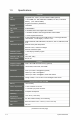
1.3 Specifications SYSTEM CPU Integrated Intel® Atom™ processor N2600 / N2800 (optional) Memory 1 x SO-DIMM, max. 2GB, DDR3 800 / 1066MHz, non-ECC, un-buffered Memory (max.
I/O Storage 2 x SATA 3Gb/s ports USB 6 x USB 2.
Others Supported OS Windows® XP 32-bit Windows® XP 64-bit (only with AMD graphics) Windows® 7 32-bit Windows® 7 64-bit (only with AMD graphics) Windows® 8 32-bit Windows® 8 64-bit (only with AMD graphics) Linux Fedora Accessories 1 x SATA 3Gb/s cable 1 x SATA power cable 1 x Support DVD (Drivers, Manual) NOTE: Specifications are subject to change without notice.
Chapter 2 Motherboard information 2.1 Before you proceed Take note of the following precautions before you install motherboard components or change any motherboard settings. CAUTION! • Unplug the power cord from the wall socket before touching any component. • Before handling components, use a grounded wrist strap or touch a safely grounded object or a metal object, such as the power supply case, to avoid damaging them due to static electricity.
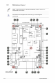
2.2 Motherboard layout NOTE: Place five screws into the holes indicated by circles to secure the motherboard to the chassis. CAUTION! Do not overtighten the screws! Doing so can damage the motherboard. 1 2 3 4 5 11.5cm(4.53in) PCIeX1 AAFP1 AMP_CON1 SPDIF_OUT1 HDMI1 SIM1 ICS 9VRS4339AL LAN1 SPEAKER SPI1 MINI_CARD1 ALC 887 SATA3G_2 SATA3G_1 ISD72 D9MGG AMD® HD7410M 7 AMD® GPU (optional) RTL 8111F 6 ISD72 D9MGG MINI_CARD2 PLX PEX8605 16.5cm(6.
Connectors/Jumpers/Slots Page 1. Digital audio connector (4-1 pin SPDIF_OUT1) 2-13 2. Line-Out / Mic-In audio connector (10-1 pin AAFP1) 2-13 3. SPI programming connector (8-pin SPI1) 2-18 4. Audio amplifier connector (4-pin AMP_CON1) 2-20 5. Serial ATA 3Gb/s connectors (7-pin SATA3G_1/2) 2-17 6. Internal speaker connector (4-pin SPEAKER) 2-15 7. LVDS connector (30-pin LVDS1) 2-21 8. VGA connector (16-pin VGA) 2-20 9. LCD inverter power setting jumper (3-pin LCD_POWER_SEL1) 2-11 10.
2-4 2.3 Screw size 2.3.
2.3.
2.4 Central Processing Unit (CPU) The motherboard comes with an integrated Intel® Atom™ processor N2600 / N2800 (optional). Integrated Intel® Atom™ processor faytech Industrial Motherboard Series Integrated Intel® Atom™ processor 2.5 System memory This motherboard comes with one Double Data Rate 3 (DDR3) Small Outline Dual Inline Memory Modules (SO-DIMM) socket.
To install a DIMM 3 To remove a DIMM Chapter 2: Motherboard information 2-7
2.6 1. Jumpers Clear RTC RAM (3-pin CLRTC1) This jumper allows you to clear the Real Time Clock (RTC) RAM in CMOS. You can clear the CMOS memory of date, time, and system setup parameters by erasing the CMOS RTC RAM data. The onboard button cell battery powers the RAM data in CMOS, which include system setup information such as system passwords. CLRTC1 1 2 2 3 Normal (Default) Clear faytech Industrial Motherboard Series Clear CMOS RAM To erase the RTC RAM: 1.
2. COM1 Ring and voltage selection (6-pin J1) J1 1 2 +12V 3 4 +5V 5 6 Ring (Default) faytech Industrial Motherboard Series COM1 Ring and voltage selection Pins 3.
4. LVDS backlight brightness control jumper (3-pin L_BRIGHTNESS1) L_BRIGHTNESS1 1 2 DC MODE (Default) PWM MODE faytech Industrial Motherboard Series LVDS backlight brightness control jumper Pins 5.
6.
2.7 Connectors 2.7.1 Rear panel connectors 1 2 3 4 5 1. HDMI port. This port is for a High-Definition Multimedia Interface (HDMI) connector, and is HDCP compliant allowing playback of HD DVD, Blu-Ray, and other protected content. 2. LAN (RJ-45) ports. These ports allow Gigabit connection to a Local Area Network (LAN) through a network hub. Refer to the table below for the LAN port LED indications.
2.7.2 1. Internal connectors Line-Out / Mic-In audio connector (10-1 pin AAFP1) This connector is for Line-Out / Mic-In audio connection. AAFP1 LINE1-JD GNDNCMIC1-JD PIN 1 A_MIC1_LA_MIC1_RLINE-RA _JD_FRONTLINE-L faytech Industrial Motherboard Series Line-Out / Mic-In audio connector 2. Digital audio connector (4-1 pin SPDIF_OUT1) This connector is for an additional Sony/Philips Digital Interface (S/PDIF) port.
3. EATX power connector (2-pin EATX_PWR1) This connector is for EATX power supply plug. The power supply plug Is designed to fit this connector in only one orientation. Find the proper Orientation and push down firmly until the connector completely fit. EATX_PWR1 +- faytech Industrial Motherboard Series EATX power connector 4. Serial port connectors [WtoB CON 9P, 1.25mm, S/T, SMT / ACES / 5027300971-001] (9-pin COM2/3/4) These connectors are for serial (COM) ports.
5. Chassis fan connector (4-pin CHA_FAN1) Connect the fan cable to the fan connector on the motherboard, ensuring that the black wire of the cable matches the ground pin of the connector. CHA_FAN1 PWMSENSEVCCGND faytech Industrial Motherboard Series Chassis fan connector CAUTION: Do not forget to connect the fan cable to the fan connector. Insufficient air flow inside the system may damage the motherboard components. This is not a jumper! Do not place jumper caps on the fan connector! 6.
7. System panel connector (10-1 pin F_PANEL1) This connector supports several chassis-mounted functions. F_PANEL1 +HD_LED PWR LED PIN 1 HD_LED+ HD_LEDGND RESETHWRST# (NC) BTN PWR PLED+ PLEDPANSWH# GND faytech Industrial Motherboard Series System panel connector • • System power LED (2-pin PWR LED) This 2-pin connector is for the system power LED. Connect the chassis power LED cable to this connector.
8. Serial ATA 3Gb/s connectors (7-pin SATA3G_1/2]) These connectors connect to Serial ATA 3Gb/s hard disk drives and optical drives via Serial ATA 3Gb/s signal cables. SATA3G_2 GNDRSATA_TXP2RSATA_TXN2GNDRSATA_RXN 2RSATA_RXP2GND SATA3G_1 GNDRSATA_RXP1RSATA_RXN1GNDRSATA_TXN 1RSATA_TXP1GND faytech Industrial Motherboard Series SATA 3.0Gb/s connectors NOTES: 9. • These connectors are set to [IDE] by default. In IDE mode, you can connect Serial ATA boot/data hard disk drives to these connectors.
10. USB 2.0 connector (10-pin USB1) This connector is for USB 2.0 ports. Connect the USB module cable to this connector, then install the module to a slot opening at the back of the system chassis. This USB connector complies with USB 2.0 specification that supports up to 480 Mbps connection speed. USB1 PIN 1 +5V USB4-_R USB4+_R GND GND GND GND USB5+_R USB5-_R +5V faytech Industrial Motherboard Series USB 2.0 connector CAUTION! Never connect a 1394 cable to the USB connector.
12. PS/2 keyboard/mouse connector (6-pin KBMS1) This connector is for an IBM PS/2-compatible keyboard or mouse. KBMS1 MS_DATA GND KB_DATA MS_CLK +5V KB_CLK PIN 1 faytech Industrial Motherboard Series PS/2 keyboard/mouse connector 13 Backlight inverter power connector [WAFER HD 5P S/T 2.0mm WHITE / PINREX / 721-81-05TW00] (5-pin INV1) Connect the backlight inverter power cable to this connector.
14. VGA connector [BOX HEADER 2X8P S/T 2.0mm SMT // PINREX / 52M-9016GBE0] (16-pin VGA) This 16-pin connector is for a VGA monitor or other VGA-compatible devices. VGA PIN 1 +5V GND NC RDDCA_DATA_R R_HSYNC R_VSYNC RDDCA_CLK_R GND DAC_R DAC_G DAC_B NC GND NC GND GND faytech Industrial Motherboard Series VGA connector 15. Audio amplifier connector [WtoB CON4P, 1.25mm, S/T, SMT // ACES / A 85025-04701] (4-pin AMP_CON1) This connector is for an external audio amplifier.
16. LVDS connector [WtoB CON 2P, 1.25mm, R/A, SMT // ACES / 8520402001] (30-pin LVDS1) This connector is for an LCD monitor that supports Low-voltage differential signaling (LVDS) interface.
18. Digital I/O connector (10-pin DIO1) This connector includes 8 I/O lines. All of the Digital I/O lines are programmable and each I/O pin can be individually programmed to support various devices. DIO1 PIN 1 DIO_P#1 (GPIO80) DIO_P#3 (GPIO82) DIO_P#5 (GPIO84) DIO_P#7 (GPIO86) +5V DIO_P#2 (GPIO81) DIO_P#4 (GPIO83) DIO_P#6 (GPIO85) DIO_P#8 (GPIO87) GND faytech Industrial Motherboard Series Digital I/O connector NOTE: To configure the I/O pins in BIOS, go to the Advanced tab > DIO Function > GPIO 1~8.
Chapter 3 BIOS setup 3.1 BIOS setup program Use the BIOS Setup program to update the BIOS or configure its parameters. The BIOS screens include navigation keys and brief online help to guide you in using the BIOS Setup program. Entering BIOS Setup at startup To enter BIOS Setup at startup: • Press during the Power-On Self Test (POST). If you do not press , POST continues with its routines.
3.2 BIOS menu screen Menu items Menu bar Configuration fields BIOS Information BIOS Version Build Date General help Choose the system default language 0202 x64 11/30/2012 CPU Information Intel(R) Atom(TM) CPU 600 @ 1.
Menu items Thehighlighted item on the menu bar displays the specific items for that menu. For example, selecting Main shows the Main menu items. The other items (Ai Tweaker, Advanced, Monitor, Boot, Tool, and Exit) on the menu bar have their respective menu items. Back button This button appears when entering a submenu. Press or use the USB mouse to click this button to return to the previous menu screen.
3.3 Main menu The Main menu screen appears when you enter the Advanced Mode of the BIOS Setup program. The Main menu provides you an overview of the basic system information, and allows you to set the system date, time, language, and security settings. BIOS Information BIOS Version Build Date Choose the system default language 0202 x64 11/30/2012 CPU Information Intel(R) Atom(TM) CPU 600 @ 1.
Administrator Password If you have set an administrator password, we recommend that you enter the administrator password for accessing the system. Otherwise, you might be able to see or change only selected fields in the BIOS setup program. To set an administrator password: 1. Select the Administrator Password item and press . 2. From the Create New Password box, key in a password, then press . 3. Confirm the password when prompted. To change an administrator password: 1.
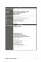
3.4 Advanced menu The Advanced menu items allow you to change the settings for the CPU and other system devices. CAUTION: Be cautious when changing the settings of the Advanced menu Items. Incorrect field values can cause the system to malfunction. > CPU > Configuration IDE > USB Configuration > Select North Bridge LVDS > Configuration Onboard CPU Configuration Configuration Parameters > APM > Panel Controller > DIO Function 3.4.
3.4.2 IDE Configuration While entering Setup, the BIOS automatically detects the presence of SATA devices. The SATA Port items show Not Present if no SATA device is installed to the corresponding SATA port. SATA Controller(s) [Enabled] [Disabled] Disables the onboard SATA controllers. [Enabled] Enables the onboard SATA controllers. Configure SATA as [IDE] Allows you to set the SATA configuration.
Power On By Ring [Disabled] [Disabled] Disables Ring to generate a wake event. [Enabled] Enables Ring to generate a wake event. 3.4.5 Panel Controller (AMD® GPU only) Backlight Brightness Setting [75] Allows you to set the backlight brightness. Select a larger number for a brighter backlight. Configuration options: [0][25][50][75][100] 3.4.6 DIO Function GPIO 1~8 [Input] Allows you to configure the digital signal of the GPIO (General Purpose Input/ Output) pins 1~8.
Onboard LAN Boot ROM [Disabled] This item appears only when you set the Onboard LAN item to [Enabled] and allows you to enable or disable the Boot ROM of the onboard LAN controller. Configuration options: [Enabled] [Disabled] 3.5 Monitor menu The Monitor menu displays the system temperature/power status, and allows you to change the fan settings. 3.5.1 CPU Temperature / MB Temperature [xxxºC/xxxºF] The onboard hardware monitor automatically detects and displays the CPU and motherboard temperatures.
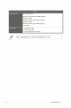
3.5.3 Chassis Q-Fan Control [Enabled] [Disabled] Disables the Chassis Q-Fan control feature. [Enabled] Enables the Chassis Q-Fan control feature. Chassis FanProfile [Standard] This item appears only when you enable the Chassis Q-Fan Control feature and allows you to set the appropriate performance level of the chassis fan. [Standard] Sets to [Standard] to make the chassis fan automatically adjust depending on the chassis temperature.
3.6.2 Full Screen Logo [Disabled] [Enabled] Enables the full screen logo display feature. [Disabled] Disables the full screen logo display feature. 3.6.3 Wait for ‘F1’ If Error [Enabled] When this item is set to [Enabled], the system waits for the F1 key to be pressed When error occurs. Configuration options: [Disabled] [Enabled] 3.6.4 Boot Option Priorities These items specify the boot device priority sequence from the available devices.
3.8 Exit menu The Exit menu items allow you to load the optimal default values for the BIOS items, and save or discard your changes to the BIOS items. You can access the EZ Mode from the Exit menu. Load Optimized Defaults This option allows you to load the default values for each of the parameters on the Setup menus. When you select thisoption or if you press , a confirmation window appears. Select Yes to load the default values.
Appendix Notices Federal Communications Commission Statement This device complies with Part 15 of the FCC Rules. Operation is subject to the following two conditions: • This device may not cause harmful interference. • This device must accept any interference received including interference that may cause undesired operation. This equipment has been tested and found to comply with the limits for a Class A digital device, pursuant to Part 15 of the FCC Rules.
KONTAKT / CONTACT Kontaktdaten, RMA-Bearbeitung Support-Nummer: +49 211 9954 8956 Global-Support: +86 755 89580612 Support-E-Mail: support@faytech.de Hersteller-Internetseite: www.faytech.com Europäisches Support- und Versandlager: faytech Service Hans-Böckler Str. 10a, 37079 Göttingen RMA-Bearbeitung Wenden Sie sich bei einem mutmaßlichen Defekt bitte immer zunächst an uns. Unsere ausgebildeten Fachkräfte helfen Ihnen gerne weiter. Liegt tatsächlich ein Defekt vor erhalten Sie über support@faytech.