Please Note We accept no responsibility for the rights of third parties with regards to any of the herein printed tables or descriptions. With this catalogue components are illustrated, features are not guaranteed. Availability and technical alterations are subject to change without prior warning. We accept no responsibility for human error or misprints within this catalogue. We offer no guarantee for the completeness of any herein printed reports.
List of Contents Inhaltsverzeichnis General Information .................................................................................................................... 6 Allgemeine Informationen ........................................................................................................... 6 High Density D-Sub Connectors ................................................................................................. 6 High Density D-Sub Steckverbinder ......................................
List of Contents Inhaltsverzeichnis Shielded Right Angled Adapter, Screwable .............................................................................. 25 Geschirmter Winkeladapter, verschraubbar .............................................................................. 25 Ordering Code, Use Contact Type and Direction of Right Angled Contacts ........................................................................................
General Information Allgemeine Informationen In terms of their outside dimensions the shells of the high density D-Sub series are the same as for the well known standard D-Sub connectors, but the number of contacts has been considerably increased. Due to the higher density of 15, 26, 44, 62 and 78 contacts, this series is ideally suited for the most modern applications in data transmission and telecommunications, as well as in measurement, regulation and control devices.
Ordering Code (High Density D-Sub Connectors) Bestellschlüssel (High Density D-Sub Steckverbinder) DIMENSIONS IN MILLIMETERS - VALUES FOR INCHES IN BRACKETS - TECHNICAL DATA SUBJECT TO CHANGE HD 01/2007 7
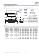
Pin: Solder Pot Termination Stift: Löttopfanschluss Dimensions Abmessungen Pin Connector, Front View Stiftsteckverbinder, Frontansicht Stamped contacts (wire size: max. AWG 22) Gestanzte Kontakte (Drahtgröße: max. AWG 22) Dimensions Abmessungen 8 Order Number Bestellnummer Shell Size Gehäusegröße Number of Contacts Polzahl CT09-15P 1 15 CT15-26P 2 26 CT25-44P 3 44 CT37-62P 4 62 CT50-78P 5 78 HD 01/2007 A B C D E F G ±0,4 +0,2 ±0,15 +0,2 ±0,4 ±0,3 ±0,3 (±0.016) (+0.008) (±0.006) (+0.
Socket: Solder Pot Termination Buchse: Löttopfanschluss Dimensions Abmessungen Socket Connector, Front View Buchsensteckverbinder, Frontansicht Stamped contacts (wire size: max. AWG 22) Gestanzte Kontakte (Drahtgröße: max. AWG 22) Dimensions Abmessungen Order Number Bestellnummer Shell Size Gehäusegröße Number of Contacts Polzahl CT09-15S 1 15 CT15-26S 2 26 CT25-44S 3 44 CT37-62S 4 62 CT50-78S 5 78 A ±0,4 (±0.016) 30,8 (1.213) 39,1 (1.539) 53,0 (2.087) 69,3 (2.728) 66,9 (2.
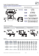
Pin: Straight PCB Termination Stift: Gerader Leiterplattenanschluss Dimensions Abmessungen Pin Connector, Front View Stiftsteckverbinder, Frontansicht Stamped contacts Gestanzte Kontakte PCB Hole Pattern (Mounting Side) Leiterplattenlochbild (Bestückungsseite) Hole Pattern 15 Contacts Lochbild 15-polig Hole Pattern 26, 44 and 62 Contacts Lochbild 26-, 44- und 62-polig Hole Pattern 78 Contacts Lochbild 78-polig Dimensions Abmessungen 10 Order Number Bestellnummer Shell Size Gehäusegröße Number of Co
Socket: Straight PCB Termination Buchse: Gerader Leiterplattenanschluss Dimensions Abmessungen Socket Connector, Front View Buchsensteckverbinder, Frontansicht Stamped contacts Gestanzte Kontakte PCB Hole Pattern (Mounting Side) Leiterplattenlochbild (Bestückungsseite) Hole Pattern 15 Contacts Lochbild 15-polig Hole Pattern 26, 44 and 62 Contacts Lochbild 26-, 44- und 62-polig Hole Pattern 78 Contacts Lochbild 78-polig Dimensions Abmessungen Order Number Bestellnummer Shell Size Gehäusegröße Number o
Pin: Right Angled PCB Termination Stift: Abgewinkelter Leiterplattenanschluss Dimensions Abmessungen Pin Connector, Front View Stiftsteckverbinder, Frontansicht 4-40 UNC-2B or M3 clinch nut on connector flange available. Mit 4-40 UNC-2B bzw. M3 Gewindeniet im Steckerflansch lieferbar.
Socket: Right Angled PCB Termination Buchse: Abgewinkelter Leiterplattenanschluss Dimensions Abmessungen Socket Connector, Front View Buchsensteckverbinder, Frontansicht 4-40 UNC-2B or M3 clinch nut on connector flange available. Mit 4-40 UNC-2B bzw. M3 Gewindeniet im Steckerflansch lieferbar.
Panel Cut-out Montageausschnitt Front Mounted Frontseitig montiert Standard, Front Mounted Standard, frontseitig montiert Float, Front Mounted (Series FW) Schwimmend, frontseitig montiert (Baureihe FW) 0.004 0.1 0.004 0.1 0.087 2.2 0.016 0.4 0.161 4.1 0.016 0.4 0.114 ±0.004 2.9 ±0.1 Shell Size Gehäusegröße 1 2 3 4 5 A B C ±0,2 (±0.008) ±0,1 (±0.004) ±0,2 (±0.008) 22,2 (0.874) 25,0 (0.984) 12,3 (0.484) 30,5 (1.201) 33,3 (1.311) 12,3 (0.484) 44,3 (1.744) 47,0 (1.850) 12,3 (0.484) 60,7 (2.390) 63,5 (2.
For Your Notes Für Ihre Notizen DIMENSIONS IN MILLIMETERS - VALUES FOR INCHES IN BRACKETS - TECHNICAL DATA SUBJECT TO CHANGE HD 01/2007 15
High Density D-Sub Crimp Connectors High Density D-Sub Crimp Steckverbinder Technical Data Technische Daten Mechanical Data Mechanische Daten Mechanical Data Mechanische Daten Shell Gehäuse Insulator Isolierkörper Signal contacts Signalkontakte Steel, tin plated; pin shell with dimples Stahl, verzinnt; Stiftgehäuse mit Kontaktnoppen Thermoplastic, glassfilled UL94V-0 Thermoplast, glasfaserverstärkt UL94V-0 Copper alloy, gold plated Kupferlegierung, vergoldet Electrical Data Elektrische Daten Electrical Da
Ordering Code (High Density D-Sub Crimp Connectors) Bestellschlüssel (High Density D-Sub Crimp Steckverbinder) DIMENSIONS IN MILLIMETERS - VALUES FOR INCHES IN BRACKETS - TECHNICAL DATA SUBJECT TO CHANGE HD 01/2007 17
Pin: Crimp Termination Stift: Crimpanschluss Dimensions Abmessungen Pin Connector without Contacts, Front View Stiftsteckverbinder ohne Kontakte, Frontansicht Dimensions Abmessungen Order Number Bestellnummer Shell Size Gehäusegröße Number of Contacts Polzahl FL09-15P7 1 15 FL15-26P7 2 26 FL25-44P7 3 44 FL37-62P7 4 62 CT50-78P7 5 78 A B C D E F ±0,4 +0,2 ±0,15 +0,2 ±0,4 ±0,3 (±0.016) (+0.008) (±0.006) (+0.008) (±0.016) (±0.012) 30,8 16,9 25,0 8,2 12,5 10,8 (1.213) (0.665) (0.984) (0.
Socket: Crimp Termination Buchse: Crimpanschluss Dimensions Abmessungen Socket Connector without Contacts, Front View Buchsensteckverbinder ohne Kontakte, Frontansicht Dimensions Abmessungen Order Number Bestellnummer Shell Size Gehäusegröße Number of Contacts Polzahl FL09-15S7 1 15 FL15-26S7 2 26 FL25-44S7 3 44 FL37-62S7 4 62 CT50-78S7 5 78 A B C ±0,4 -0,2 ±0,15 (±0.016) (-0.008) (±0.006) 30,8 16,4 25,0 (1.213) (0.646) (0.984) 39,1 24,7 33,3 (1.539) (0.972) (1.311) 53,0 38,5 47,04 (2.
Stamped Crimp Contacts Gestanzte Crimpkontakte Pin Stift Socket Buchse Technical Data Technische Daten Ordering Information Bestellinformationen The stamped crimp contacts for high density D-Sub connectors are available in reels of 300, 2,000 pcs or 10,000 pcs. The contacts are selectively gold plated in the mating area. For crimping tools please see page 25. Die gestanzten Kontakte für High Density D-Sub Steckverbinder sind auf einer Rolle zu 300, 2.000 Stück oder zu 10.000 Stück lieferbar.
Turned Crimp Contacts Gedrehte Crimpkontakte Pin Stift Socket Buchse Ordering Information Bestellinformationen Technical Data Technische Daten The turned crimp contacts are available in standard and MIL versions. For the standard contacts, the plating is 0.2 μm (8 microinches) gold over nickel, and for the MIL contacts it is 1.3 μm (50 microinches) gold over nickel. For crimping tools please see top of page 26. Die gedrehten Crimpkontakte sind in einer Standard- sowie einer MIL-Ausführung lieferbar.
Accessories Zubehör Clinch Nuts Einnietmuttern Mounting Type Befestigungsart T Z TS ZS Self Locking Selbstsichernd — — • • Surface Oberfläche Tin-plated or zinc-plated verzinnt oder verzinkt Ordering Example Bestellbeispiel Pin connector, clinch nut 4-40 UNC, 9 contacts Stiftsteckverbinder, Einnietmutter 4-40 UNC, 9-polig FLT09-15P7 FLT09-15P7 Threaded Spacers Abstandsbolzen Rear Riveted Rückseitig vernietet Ordering Example Bestellbeispiel Pin connector, 15 contacts, straight PCB termination, rea
Frontside Spacers and Rearside Spacers or Snap-in Bolts Frontseitiger Abstandsbolzen und rückseitiger Abstands- oder Schnappbolzen Frontside Inner Thread 4-40 UNC Frontseitiges Innengewinde 4-40 UNC Frontside Inner Thread M3 Frontseitiges Innengewinde M3 Through Hole Ø 3.1 mm (Ø 0.122”) Durchgangsloch Ø 3,1 mm Frontside Inner Thread, Rearside Snap-in bolt (Recommended Diameter of the Assembly Drilling 3.0 mm ±0,1 (0.118” ±0.
Snap-in Bolts for PCB Mounting Schnappbolzen für Leiterplattenmontage For PCBs with 1.6 mm (0.063”) Thickness (Recommended Diameter of the Assembly Drilling 3.0 mm ±0,1 (0.118” ±0.004)) Für Leiterplatten mit 1,6 mm Stärke (empfohlener Durchmesser der Montagebohrungen 3,0 mm ±0,1) For PCBs with 2.4 mm (0.094”) and 3.2 mm (0.126”) Thickness (Recommended Diameter of the Assembly Drilling 3,0 mm ±0,1 (0.118” ±0.
Shielded Right Angled Adapter, Screwable Geschirmter Winkeladapter, verschraubbar FAW1PS... Ne w Ne pro uh du eit ct Special Features Besondere Merkmale - May be used as a bracket adaptor, e.g.
Ordering Code Bestellschlüssel 26 HD 01/2007 TECHNISCHE ÄNDERUNGEN VORBEHALTEN – MAßE IN MILLIMETER (INCHES IN KLAMMERN)
Technical Data Technische Daten Mechanical Data Mechanische Daten Mechanical Data Mechanische Daten Mating force per signal contact Steckkraft pro Signalkontakt Unmating force per signal contact Ziehkraft pro Signalkontakt max. torque * max. Anzugsmoment * d 3,4 N t 0,2 N 40 Ncm (0,295 ft.lb.
Dimensions Abmessungen Order Number Bestellnummer FAW1 FAW2 FAW3 FAW4 A B C D ±0,3 ±0,2 ±0,15 ±0,2 (±0.012) (±0.008) (±0.016) (±0.008) 30,8 16,9 25,0 16,4 (1.213) (0.665) (0.984) (0.646) 39,1 25,2 33,3 24,7 (1.539) (0.992) (1.311) (0.972) 52,8 38,9 47,0 28,5 (2.079) (1.532) (1.850) (1.122) 69,3 55,3 63,5 54,9 (2.728) (2.177) (2.500) (2.
Crimping Tools Crimpwerkzeuge For Stamped Contacts Für gestanzte Kontakte Hand Crimping Tool for Reels of 300 pcs Handcrimpzange für Rollen mit 300 Stück The FCT hand crimping tool F1839 is suitable for use with stamped contacts on a reel. With this tool, contacts for wire sizes AWG 24 –28 can be easily crimped. The hand crimping tool has manual adjustment for contact alignment, a waste cutter for contacts on a reel and contact centring to ensure a fast, inexpensive crimping process, entry from left side.
For Turned MIL- and Standard Contacts Für gedrehte MIL- und Standardkontakte Hand Crimping Tool Handcrimpzange Order number: Bestellnummer: M22520/2-01 When crimping contacts it is necessary to use a corresponding insert. Beim Crimpen muss immer ein Einsatz für den entsprechenden Kontakt verwendet werden.
Order Number Index Bestellnummern - Index C CT09-15P ______________ CT09-15P1 _____________ CT09-15P1-1432 _________ CT09-15P1-1779 _________ CT09-15P5-L228 _________ CT09-15P5-L229 _________ CT09-15P5L222 _________ CT09-15S ______________ CT09-15S1 _____________ CT09-15S5-L222 _________ CT09-15S5-L228 _________ CT09-15S5-L229 _________ CT15-26P ______________ CT15-26P1 _____________ CT15-26P5-L228 _________ CT15-26P5-L229 _________ CT15-26P5L222 _________ CT15-26S ______________ CT15-26S1 _____________ CT1