
Datasheet

fctgroup.com I 21
Materials and Platings
Materialien und Oberflächen
Mechanical Data
Mechanische Daten
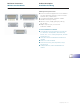
Modifications
Modifikationen
All FCT D-Sub connectors (including crimp versions etc.) are
available in many different combinations of materials and pla-
tings. For example, shells can be supplied in a non – magnetic
version made of brass, which can be electroless nickel, or gold
plated for use in aerospace technology.
Alle FCT D-Sub Steckverbinder (auch Crimp Versionen, usw.)
sind in vielen verschiedenen Material- und Oberflächenkombina-
tionen erhältlich. So z. B. Gehäuse in nichtmagnetischer Ausfüh-
rung aus Messing bzw. chemisch vernickelte oder vergoldete
Gehäuse für Luft- und Raumfahrtanwendungen.
Electrical Data
Elektrische Daten
Miniature Connectors
Miniatur Steckverbinder
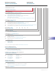
Technical Details
Technische Hinweise
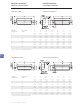
Shell Steel
Gehäuse
Stahl
Type / Type F FH FM
Insulator
Polyester, glass fiber filled
(UL94V-0), white
Polyester, heat resistant, glass filled
(UL94V-0), natural
Polyester, glass fiber filled (UL94V-0), green
Isolierkörper
Polyester, glasfaserverstärkt
(UL94V-0), weiß
Polyester, hochtemperaturbeständig,
glasfaserverstärkt (UL94V-0), natur
Polyester, glasfaserverstärkt (UL94V-0), grün
Relative temperature index
according to UL 746 B
125 °C (257 °F) 150 °C (302 °F) 130 °C (266 °F)
rel. Temperaturindex nach UL 746 B
Heat deflection temperature limit
according to DIN 53461 HDT/A
200 °C (392 °F) ≥255 °C (≥491 °F) 210 °C (410 °F)
Formbeständigkeitstemperatur
nach DIN 53461 HDT/A
Sub temperature limit
-55 °C (-67 °F) -55 °C (-67 °F) -55 °C (-67 °F)
Untere Grenztemperatur
Shell plating (standard) Tin plated over nickel
Yellow chromate over zinc plating
Not RoHS compliant
Gehäuseoberfläche (Standard)
verzinnt über Nickel
verzinkt und gelb chromatiert
nicht RoHS konform
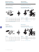
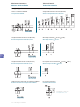
Shell (standard) Pin connector shell with dimples Pin connector shell without dimples
Gehäuse (Standard)
Stiftsteckverbindergehäuse mit Kontaktnoppen Stiftsteckverbindergehäuse ohne Kontaktnoppen
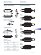
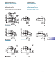
Shell (K120) Tin plated over nickel, pin connector shell with dimples
Gehäuse (K120)
verzinnt über Nickel, Stiftsteckverbindergehäuse
mit Kontaktnoppen
Shell (K121)
Tin plated over nickel, pin connector shell
without dimples
Gehäuse (K121)
verzinnt über Nickel, Stiftsteckverbindergehäuse
ohne Kontaktnoppen
Contact material Copper alloy
Kontaktmaterial Kupfer-Legierung
Mating force per signal contact
≤ 3,4 N
Steckkraft pro Signalkontakt
Unmating force per signal contact
≥ 0,2 N
Ziehkraft pro Signalkontakt
max. torque *
40 Ncm (0,295 ft.lb.)
max. Anzugsmoment *
40 Ncm
* Not for locking screws / * Nicht für Verriegelungsschrauben
Current rating at room temperature
5 A
Maximale Stromstärke bei Raumtemperatur
Test voltage between 2 contacts / shell and contact
1200 V / 1 min.
Prüfspannung zwischen 2 Kontakten bzw. Kontakt und Gehäuse
Meets transition resistance requirements per contact pair
in line with DIN 41652:
Erfüllt Übergangswiderstand pro Kontaktpaar
nach DIN 41652 für:
_ Straight contacts
≤ 10 mΩ
_ gerade Kontakte
_ Right angled contacts
≤ 25 mΩ
_ abgewinkelte Kontakte
_ Right angled contacts - 50 way
≤ 35 mΩ
_ abgewinkelte Kontakte bei 50 Polen
Insulation resistance between contacts
≥ 5000 MΩ
Isolationswiderstand Kontakt / Kontakt
Volume resistivity
10
16
Ω cm
Spezifischer Durchgangswiderstand
Dielectric strength
50 kV / mm
Spezifische Durchschlagsfestigkeit