
Datasheet
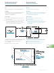

Test Report, Derating Diagram
Test
Electrical load derating in accordance with DIN 41640 Part 3.
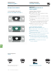
Test Object
Mated mixed layout connectors FM8W8P and FM8W8S fully
loaded with eight 40 Amp high power crimp contacts
FMP004P103 and FMP004S103.
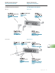
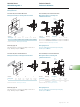
Test Procedure
I In accordance with DIN 41640, Part 3 all contacts were
connected in series.
I At various electrical intensities the following measurements
were taken: the temperature of the connector at the
warmest point and the ambient temperature at a distance
of (1.969 ") from the connector (see illustration).
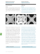
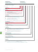
The above electrical load derating curve illustrates the maximum
permissible current in relation to ambient temperature i.e.:
I The maximum permissible load at 20 °C (68 °F)
is over 40 Amp
I At 100 °C (212 °F) it is still over 25 Amp
Testbericht, Diagramm Strombelastbarkeit
Messung
Strombelastbarkeit nach DIN 41640 Teil 3.
Messobjekt
Zusammengesteckte Mixed Layout Steckverbinder FM8W8P und
FM8W8S vollbestückt mit 8 Stück 40 A Hochstrom Crimpkon-
takten FMP004P103 und FMP004S103.
Messanordnung
I nach DIN 41640 Teil 3 wurden alle Kontakte
in Reihe geschaltet.
I bei verschiedenen Stromstärken wurde jeweils die
Temperatur des Steckverbinders an der wärmsten Stelle und
die Umgebungstemperatur in 50 mm Abstand gemessen
(siehe Abbildung).
Die obenstehende Strombelastbarkeitskurve (Derating-Kurve)
zeigt den maximal zulässigen Strom in Abhängigkeit von der
Umgebungstemperatur. Zur Erläuterung:
I bei 20 °C liegt die maximale Belastbarkeit über 40 A
I bei 100 °C liegt sie immer noch bei über 25 A
fctgroup.com I 133
Mixed Layout Connectors
Mischpolsteckverbinder
General Information
Allgemeine Information