
Data Sheet


FSC-BT1006A Datasheet
Shenzhen Feasycom Technology Co.,Ltdwww.feasycom.com
-38-
IPC/JEDEC J-STD-033.
Note: The shipping tray cannot be heated above 65°C. If baking is required at the higher temperatures displayed in the
below Table 27, the modules must be removed from the shipping tray.
Any modules not manufactured before exceeding their floor life should be re-packaged with fresh desiccate and a new
humidity indicator card. Floor life for MSL (Moisture Sensitivity Level) 3 devices is 168 hours in ambient environment
30°C/60%RH.
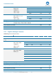
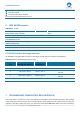
Table 27:Recommended baking times and temperatures
MSL
125°C Baking Temp.
90°C/≤ 5%RH Baking Temp.
40°C/ ≤ 5%RH Baking Temp.
Saturated @
30°C/85%
Floor Life Limit
+ 72 hours @
30°C/60%
Saturated @
30°C/85%
Floor Life Limit
+ 72 hours @
30°C/60%
Saturated@
30°C/85%
Floor Life Limit
+ 72 hours @
30°C/60%
3
9 hours
7 hours
33 hours
23 hours
13 days
9 days
Feasycom surface mount modules are designed to be easily manufactured, including reflow soldering to a PCB.
Ultimately it is the responsibility of the customer to choose the appropriate solder paste and to ensure oven
temperatures during reflow meet the requirements of the solder paste. Feasycom surface mount modules conform to
J-STD-020D1 standards for reflow temperatures.
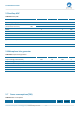
The soldering profile depends on various parameters necessitating a set up for each application. The data here is
given only for guidance on solder reflow.
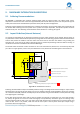
210
217
℃
250
A
B C D
1 2
0
25
3 4 5 6
min
E
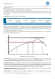
Figure 19: Typical Lead-free Re-flow
Pre-heat zone (A) — This zone raises the temperature at a controlled rate, typically 0.5 – 2 C/s. The purpose of this
zone is to preheat the PCB board and components to 120 ~ 150 C. This stage is required to distribute the heat
uniformly to the PCB board and completely remove solvent to reduce the heat shock to components.
Equilibrium Zone 1 (B) — In this stage the flux becomes soft and uniformly encapsulates solder particles and spread
over PCB board, preventing them from being re-oxidized. Also with elevation of temperature and liquefaction of flux,
each activator and rosin get activated and start eliminating oxide film formed on the surface of each solder particle and
PCB board. The temperature is recommended to be 150 to 210 for 60 to 120 second for this zone.
Equilibrium Zone 2 (C) (optional) — In order to resolve the upright component issue, it is recommended to keep the
temperature in 210 – 217 for about 20 to 30 second.
Reflow Zone (D) — The profile in the figure is designed for Sn/Ag3.0/Cu0.5. It can be a reference for other lead-free