
Data Sheet


FSC-BT986 Datasheet
Shenzhen Feasycom Technology Co., Ltd www.feasycom.com
-10-
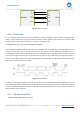
Module Host
TX RX
RX
TX
GND
GND
RTS
RTS
CTS
CTS
Figure 4: UART Connection
4.3.2 I2C Interface
I2C is a two-wire, bi-directional serial bus that provides a simple and efficient method of data exchange between
devices. The I2C standard is a true multi-master bus including collision detection and arbitration that prevents data
corruption if two or more masters attempt to control the bus simultaneously.
FSC-BT986 has I2C master which supports 100Kbps and 400Kbps.
Data is transferred between a Master and a Slave synchronously to SCL on the SDA line on a byte-by-byte basis. Each
data byte is 8-bit long. There is one SCL clock pulse for each data bit with the MSB being transmitted first. An
acknowledge bit follows each transferred byte. Each bit is sampled during the high period of SCL; therefore, the SDA
line may be changed only during the low period of SCL and must be held stable during the high period of SCL. A
transition on the SDA line while SCL is high is interpreted as a command (START or STOP). Please refer to the following
figure for more details about I2C Bus Timing.
Figure 5: I2C Bus Timing
The device on-chip I2C logic provides the serial interface that meets the I2C bus standard mode specification. The I2C
port handles byte transfers autonomously. The I2C H/W interfaces to the I2C bus via two pins: SDA and SCL. Pull up
resistor is needed for I2C operation as these are open drain pins. When the I/O pins are used as I2C port, user must set
the pins function to I2C in advance.
4.3.3 USB Device Controller
USB2.0 fullspeed,4Eps, support host mode.