
Data Sheet


FSC-BT1026 Datasheet
Shenzhen Feasycom Technology Co.,Ltd
www.feasycom.com
-8-
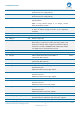
Alternative function: Differential right line output, positive
48
AUDIO_HPL_N/ SPK_LN
A
Headphone/speaker differential left output, negative.
Alternative function: Differential left line output, negative
49
AUDIO_HPL_P/ SPK_LP
A
Headphone/speaker differential left output, positive.
Alternative function: Differential left line output, positive
50
GND
Vss
Power Ground
51
RF_OUT
RF
Bluetooth transmit/receive.
Note 9
52
GND
Vss
Power Ground
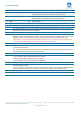
Module Pin Notes:
Note 1
The internal output of 1.8 V power supply provides maximum 30mA current, and the specific use
method can see the application circuit diagram
Note 2
Provid voltage reference to I/O, such as:PIO, UART, SPI, I
2
S, PCM,etc
Note 3
Regulator enable input. Can also be sensed as an input.
Regulator enable and multifunction button. A high input (tolerant to VBAT) enables the on-chip
regulators, which can then be latched on internally and the button used as a multifunction input.
* Reset this pin for at least 100ms after VBAT_IN and VDD_IO is up, then set this pin for more than 100
ms (can use MCU/button/delayed circuit to achieve this) to start the system.
Note 4
Using USB function and Lithium battery charging function, the pin should connect 5V voltage
Note 5
1, Alternate I
2
C function
2, I
2
C Serial Clock and Data.
It is essential to remember that pull-up resistors on both SCL and SDA lines are not provided in the
module and MUST be provided external to the module.
Note 6
For customized module, this pin can be work as I/O Interface.
Note 7
1, When the Pin33(BAT_IN) with a 3V3~4V2
this pin outputs 2V8 ~ 3V0 (maximum current: 50mA)
2, when the No. 39 PIN (VCC_CHG) with a 5V input pin,
this pin outputs 3.2V ~ 3.4V (maximum current: 50mA)
Note 8
Analog input voltage range: 0~ 1.8V
Note 9
By default, this PIN is an empty feet. This PIN can connect to an external antenna to improve the
Bluetooth signal coverage.
To use an external antenna, the position of an 0Ω resistor needs to be changed to disconnect the
on-board antenna and connect to the external antenna; Or contact Feasycom for modification.