
User Guide


Features and Operating Procedures
Reduced Pressure Backflow Preventer
The FEBCO Reduced Pressure Backflow Preventer Assembly consists of two independently operating, spring loaded check valves with a pres-
sure differential relief valve located between the two checks. The pressure drop across the first check valve is approximately 7.0psid with no
flow. The relief valve consists of a hydraulically balanced diaphragm with the high pressure side hydraulically connected to the upstream side of
the first check. The low pressure side is hydraulically connected to the reduced pressure zone, thus the relief valve remains closed during nor-
mal operation. The low pressure side of the diaphragm is spring loaded to force the relief valve open when the pressure drop across the first
check (and across the diaphragm) reduces to approximately 3.0psid. A complete assembly includes two shutoff valves and four test cocks.
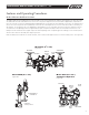
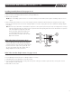
Example sectional views below show typical components and flow passages with corresponding pressure readings (no flow conditions) at the
various locations within the assembly with 100psi line pressure.
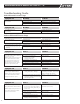
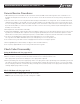
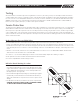
NOTE: The 880V, when installed in the vertical orientation, must include vertical support under the second check body section. (See Figure #2.)
Inlet Shutoff
Outlet Shutoff
Second
Check
Relief Valve
First Check
Reduced
Pressure
Zone
Model 860 (2
1
/2"-10")
Figure #1
Inlet Shutoff
Outlet Shutoff
Second
Check
Relief
Valve
First Check
Reduced
Pressure
Zone
Model 880V (2
1
/2"-10")
Standard Confi guration
Figure #3
Vertical support for
second check
Installed in
vertical position
Model 880V (2
1
/2"-10")
Figure #2
93
PSI
100
PSI
93
PSI
92
PSI
100
PSI
92
PSI
3
MAINTENANCE MANUAL MODELS 860 & 880V 2
1
/2" – 10"
IOM-F-860_880V.indd 3 7/11/08 10:45:26 AM