
User Guide

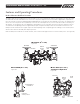


General Service Procedures
1. FEBCO backflow prevention assemblies can be serviced with commonly available tools and are designed for ease of maintenance. The
assemblies are designed to be serviced in line, so the unit should not need to be removed from the line during servicing. NO special tools
required.
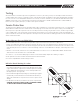
2. The most common cause of check fouling and relief valve discharge is dirt and debris in the seating areas. The line should be flushed clean
of debris before installation of the assembly. To flush the line after installation of the assembly, slowly close the inlet shutoff valve, remove
the covers and spring assemblies of both check valves and open the inlet shutoff valve to allow sufficient flow of water through the assem-
bly to clear all sand, debris, etc. from the line. If debris in the water continues to cause fouling, a strainer may be installed upstream of the
assembly. (Check local codes.)
3. Rinse all parts with clean water before reassembly.
4. Carefully inspect diaphragms, seals and seating surfaces for damage or debris. If the check valve seat disc has been severely cut at the seat
ring diameter, the assembly has been subjected to extremely high and repeated back pressure. Either thermal water expansion or water
hammer are the most likely causes. If back pressure persists, consider installation of a pressure relief valve downstream of the assembly.
5. Use caution to avoid damaging any guiding surfaces while handling parts. Do not force parts together.
The o-ring seals used in FEBCO assemblies require only a small tightening force to insure a positive seal.
6. Test unit after servicing in accordance with the locally approved test method to ensure proper operation.
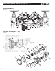
7. Refer to applicable parts list and cut-a-ways (See pages 10-15 for visual aid information).
8. Use only factory supplied lubricant or Dow Corning FS1292 (Fluorosilicone) grease.
Check Valve Disassembly
Spring Module Removal (See pages 10-11)
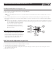
1. Slowly close outlet shutoff valve and inlet shutoff valve. Bleed residual pressure by opening #4, #3, and #2 test cocks.
2. Remove cover bolts, removing the two bolts last that are located next to the retainer pin. Remove cover.
Note: Spring module is positioned in the body by the cover. Spring module is captured.
3. Remove pivot bearing (item 13) from the upper spring retainer of the spring module. Inspect pivot bearing (item 13) and bearing socket (item
15). Small hole in bearing socket indicates replacement is required. Remove retaining clip (item 5.1) from groove on one end of the load pin
(item 7). Hold spring module with one hand while sliding out load pin (item 7) from arm (item 4). Lift out spring module and inspect for wear
or damage. Replace spring module if necessary .
Check Disk Removal (See pages 10-11)
1. Remove jam nut (item 16) and washer (item 17) from check disc stem threads. Lift the arm and remove the check disc (item 6). Inspect
sealing surface for debris or damage. Replace check disc if necessary.
Note: When jam nut (item 6) is tight, check disc is designed to “wobble.”
6
MAINTENANCE MANUAL MODELS 860 & 880V 2
1
/2" – 10"
IOM-F-860_880V.indd 6 7/11/08 10:45:27 AM